Tideway Tunnel Lining: Design Optimization of the Tunnel Lining

By Jane Hampton, Enrica Vardaro, Anna Simic and Jose Flors
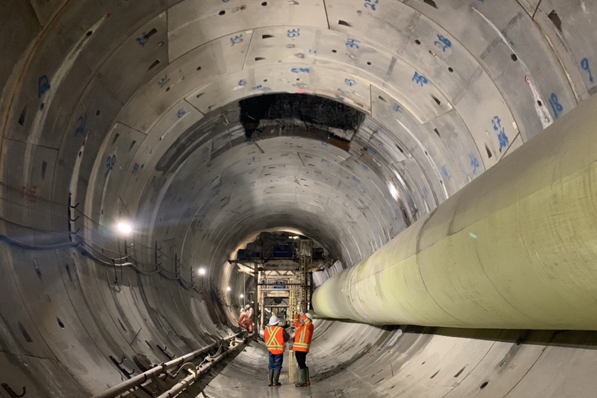
At the heart of the capital, the largest project in the U.K. water industry is underway. Tideway is a new combined storage transfer system, commissioned to provide London’s sewage network with additional capacity and prevent pollution of the River Thames. The colossal scheme consists of a 16 mile-long TBM-bored tunnel with numerous shafts, associated outfalls and surface structures along its route. The contract for the Central section, the longest and most challenging of the three, consists of 7.5 miles of tunnel and eight worksites with deep inlet shafts and ancillary structures. The Central contract tunnel primary lining has an internal diameter of 25.5 ft and has been constructed using mainly steel fiber reinforced precast segmental lining. A fiber reinforced concrete secondary lining reduces the finished internal diameter down to 24 ft . The tunnel primary lining is required to sustain high internal surge pressures and to limit water ingress and egress through the joints to a negligible amount without the contribution of the secondary lining. The biggest design challenge was to produce a single design solution for the primary lining crossing different ground conditions.
History
London’s current sewer system is over 150 years old and has reached its capacity, with combined sewer outflow (CSO) discharges into the River Thames becoming a frequent event. Since the sewage system was designed by Joseph Bazalgette in the 1860s, London’s population has more than doubled and the area of permeable surfaces decreased. Consequently, wastewater and surface water run-off has increased dramatically, and the current sewer system is unable to cope. In fact, just 2 mm of rainfall can result in raw sewage being discharged into the River Thames via combined sewer overflows (CSOs).
In an effort to upgrade the sewage network, and to ensure the quality of the River Thames complies with the European Urban Wastewater Treatment Directive (EU 1991), the Tideway project was commissioned.

Tideway Central Section
The contract for the Central section involved the design of nine shafts along with associated outfalls and surface structures along the route of the 25.5 ft ID TBM bored tunnel. The main tunnel has been constructed in two drives; westbound with an approximate length of 3 miles, and eastbound with an approximate length of 5 miles. The launch of the TBMs for the Central section towards east and west took place from the Kirtling Street Shaft inside two SCL adits due to space constraints in the shaft.
Geology
The main tunnel of Tideway Central contract of the Central section in the London Basin consists of Made Ground, Alluvium, River Terrace Deposits, London Clay Formation, Harwich Formation, Lambeth Group, Thanet Sand Formation and Chalk.
Over the course of the Central section, from the Carnwarth Road site to the Chambers Wharf site, the main tunnel encounters major changes in the geological stratigraphy.
The Tideway Central main tunnel lies within the geological province of the London basin and covers a range of different ground conditions. The geological stratigraphy that the main tunnel encountered during its excavation, from west to east, transitions from London Clay into Lambeth Group with interlayers of cohesive and granular strata, through the Thanet Sands with interlayers of sand and silty deposits before reaching the Chalk strata at Tideway East’s Chambers Wharf site. Groundwater is present in the surface superficial deposits of alluvium and the River Terrace Deposits, supported by the underlying, low-permeability London Clay Formation. This is referred to as the “upper aquifer” and it is tidally influenced by the River Thames.
Groundwater is also present in the Harwich Formation at the base of the London Clay, in granular units in the upper section of the Lambeth Group and particularly in the Channel Sands. These variable water-bearing strata are collectively termed the “intermediate aquifer”.
The main water-bearing sequence is known as the ‘lower aquifer’ and comprises of the Chalk, the overlying Thanet Sand Formation, the granular Upnor Formation and Lower Mottled Beds which form the basal units of the Lambeth Group.

Main Tunnel Performance Requirements
Tideway’s design specification for tunnels, shafts and junctions states that the main tunnel shall be provided with a primary and secondary lining to ensure that, throughout the required 120 year design life of the works, the minimum performance requirements are met. The minimum performance requirements for the completed tunnel include:
- Withstand all reasonably foreseeable external loads
- Withstand internal hydraulic pressures
- Meet water tightness criteria
- Meet durability criteria
- Prevent excessive ground movements
- Prevent aquifer contamination

One Tunnel Lining Solution for the Whole Central Section Drive
One of the main challenges encountered during the design of the main tunnel lining was to provide a unique solution for the lining that would satisfy structural and minimum watertightness performance requirements without the contribution of the secondary lining to improve time and cost efficiency. Internal loading conditions varied from empty case to a maximum internal surge pressure and together with an extensive variability in the external ground conditions they would impact the tunnel lining in many different scenarios.
As the primary tunnel lining would act as the primary means of watertightness, extensive analysis was carried out to assess the potential opening of the joints during the maximum internal surge.
The primary lining of the main tunnel was proven to be able to meet both the structural and watertightness requirements independently and therefore the cast in place fiber concrete secondary lining was only required to provide additional durability assurance in accordance with the Works Information of the project which required a two-barrier system to meet structural, watertightness and durability requirements.

Primary Tunnel Lining
The tunnel was excavated and constructed using an Earth Pressure Balance (EPB) Tunnel Boring Machine (TBM). The cutting head diameter was 29 ft. Behind the cutting head the shield diameter was 28.8 ft. This difference in radius between the cut radius and the diameter of the tail skin creates an annulus of 1+in. which allows for the ground deformation and settlements to occur.
During the excavation, the TBM applied a face pressure to balance the forces within the ground and to control the ground deformation and settlements. The pressure is applied by regulating the volume of spoil in the plenum and by rams, which allowed the TBM to advance. The working limit of the TBM maximum operating pressure was 5.3 bar (530 kPa). As the TBM advanced, the precast concrete segmental rings were installed to form the primary lining. Each ring has five “ordinary” segments, two top segments and a key with a thickness of Ts=13.8in.
After the erection of the ring, the 6 in. annulus between the excavation diameter and the external diameter of the lining was grouted through the tail skin. All segments contain steel fiber reinforcement, with additional traditional rebar reinforcement cages incorporated where a more robust ring was required, such as at the first 10 rings and last 10 rings of each drive, at the junctions with the connection tunnels, either side of the Blackfriars Shaft site and where drift filled hollows (pingos) would have been encountered.
The segmental tunnel lining has been designed to sustain external and internal water pressures of up to 6 bar associated with maximum surge event corresponding to an internal hydraulic grade line of 341 ft ATD as per Works Information requirements, limiting water ingress/egress to a negligible amount. The seal is created by the inclusion of cast-in ethylene propylene diene monomer (EPDM) gaskets in all segments. The gaskets are supplied as a continuous loop with the joints formed to the correct angles for each type of segment. Furthermore, the joint formation has been designed to minimize the additional rubber material forming the joint to avoid hard spots in the gaskets. The gaskets were pressure tested to 10 bar pressure with 0.4 in. offset and a 1/8th in. gap between bearing surfaces in a rig to model a cruciform joint arrangement.

Design Loadings
During the design of the Main tunnel, two different ground water profiles were assumed for higher and lower groundwater conditions accounting for the rising and lowering of the lower aquifer in the future. In addition upper and lower bound geotechnical parameters were considered during the design including the maximum and minimum earth pressure coefficient (Κ0,min, Κ0,max).
All the load combinations were simulated for upper and lower bound geotechnical parameters and maximum and minimum groundwater level and included the following loadings:
- Maximum internal water pressure
- Primary and Secondary grouting pressure;
- Operational surface surcharge at ground level;
- Allowance for future development at ground level;
Temporary handling and stacking loads, gantry wheel loads, ram forces and the effects of steps, lips and ring build tolerances were considered using separate empirical calculations.
Seven characteristic geological sections, considering full face ground conditions or mixed face ground conditions, were investigated along the whole route to reflect different ground conditions where the effect of the above loads was assessed.

Numerical Analysis
In line with current best design practice for this type of structure, two different numerical modelling packages have been used. The soil-structure interaction modelling was carried out using the geotechnical finite element software PLAXIS 2D. This software was used to indicate the worst design scenarios for the tunnel lining where only the effect of radial joint was taken into account.
In addition to the PLAXIS analyses, a structural model using LUSAS 3D software with both radial and circumferential joints modelled explicitly was developed to investigate the influence of the segment joints on the behavior of the lining.
The purpose of these analyses was to assess the behavior of the primary lining under all loading conditions, in particular during the surge mode and the influence of this loading on the lining joint, without considering any contribution of the secondary lining.

2D Analyses in PLAXIS
Two typical soil models were used to simulate the soil behavior: the Mohr-Coulomb (MC) and the Hardening Soil (HS). For the design of the precast tunnel lining, superficial deposits were modelled with Mohr-Coulomb model which represents soil stiffness in the in-situ stress state. However, to account for stress-dependency of the stiffness moduli when the soil stiffness increases with stress, the soil constitutive model for Thames Group, Lambeth Group, Thanet Sand and Chalk were based on Hardening Soil model.
The tunnels were constructed with the use of an EPBM which provides a support pressure to the tunnel face during the excavation to counter balance the earth and water pressure acting at the face of the excavation. The provided support face pressure minimizes the movement of the surrounding soils and subsequently the surface settlements. However, an amount of the soil mass around and ahead of the excavation will relax inducing a three-dimensional phenomenon. As a result of the relaxation of the surrounding soil mass, a radial displacement around the excavation will occur, leading to increased strain values around the excavation and consequently reduced stiffness of the surrounding soil.
In order to simulate this three-dimensional effect, a range of relaxation values, based on the solution proposed by Panet (1979) were considered for each material type and adopted in the 2D finite element (FE) analysis, considering the properties of the surrounding soil, the radius of the tunnel and the method of construction. The tunnel lining was modelled as curved plates and was characterized by linear elastic two-dimensional plate elements with axial, shear and flexural resistances.
The lining was assigned with isotropic stiffness properties and was modelled as a plate with no joints and the effect of the joints between segments of the tunnel lining was modelled by reducing the effective stiffness. The effective lining stiffness was calculated using the approach proposed by Muir-Wood (1975).
A second analysis was performed with the tunnel lining modelled as volume elements and was characterized by linear elastic two-dimensional volume elements with axial, shear, and flexural resistances. The primary lining was assigned with isotropic stiffness properties and was modelled with joints between the segments, which were prescribed with compressive and shear capacities, but zero tensile capacity. The aim of this additional analysis was to simulate the actual opening of the joints between the segments.
3D Analyses in LUSAS
The 3D finite element software LUSAS was used to create three models to investigate the influence of the segment joints on the behavior of the lining. For each model, spring supports, with stiffnesses derived from PLAXIS 2D output, were used to represent the interaction between the lining and the surrounding ground.
In the first LUSAS 3D analysis the tunnel lining was modelled as a continuous ring with no joints between the segments but with orthotropic stiffness to incorporate the effect of the joints between the segments as used in the PLAXIS 2D analysis.
In the second LUSAS analysis the tunnel lining was modelled as a shell element introducing joints between the segments with only compressive, but no tensile capacity to simulate the actual opening of the joint when the lining was subject to internal pressure.
In the third LUSAS analysis, the tunnel lining was modelled as consecutive segmental rings using dowels in the longitudinal direction to connect the rings. The consecutive segmental rings were modelled as shell elements introducing radial joints between the segments with compressive capacity but no tensile capacity.
Conclusions
For all models the stresses in the lining were within the capacity of the 13.75 in. thick fiber reinforced precast concrete tunnel section under all loading conditions ignoring any possible contribution from the secondary lining.
With particular consideration to the internal surge, where the lining would try to expand and opening the joints undermining the watertightness requirements, it was possible to demonstrate that the predicted joint opening for the most onerous scenarios was within the 1/8th in limit which the gaskets were tested for and therefore indicated that the primary lining alone is able to provide sufficient watertightness during the most extreme surge event.
Main Tunnel Secondary Lining
The secondary lining is formed of steel fiber reinforced concrete (SFRC) to aid its ability to comply with the stringent durability requirements. Additional advantages of using SFRC includes significantly improved construction costs, time, and reduced carbon dioxide emissions.
The primary lining has been designed to be capable of carrying the external and internal design loads of the main tunnel without support from the secondary lining. Nonetheless, the secondary lining will attract a share of these loads and has been designed on this basis.

Shutter and Striking Time
The SFRC secondary lining is cast in place using a full circular shutter, eliminating the need for radial construction joints.
A typical shutter length of 42 ft, travelling along the tunnels, was selected to tie into the length of the primary lining segments – 7 No. segmental lining rings of 6 ft length.
In depth analysis of the early age strength development of the concrete led to a reduction in the required striking strength of the secondary lining (6.5 MPa cylinder strength). Extensive testing was undertaken to ensure a robust concrete mix was achieved that delivers the strength requirements. Through reducing the striking strength requirement of the secondary lining, the time taken from pouring the concrete to removing the shutter has been greatly reduced, improving the production rate of construction.
Design Development
A primary tunnel lining assessment was carried out with the cast in place steel fiber reinforced concrete (SFRC) secondary lining designed to meet the durability criteria, where the segmental primary lining was re-designed to meet the structural and water tightness minimum performance requirements for the Main Tunnel alone.
Through carrying out in-depth analyses for the primary and secondary tunnel lining options, a more extensive understanding of the geological medium, ground parameters and soil-structure interaction was established. Based on the knowledge gained through design development and collaboration with the main contractor, FLO JV (a joint venture between Ferrovial Construction and Laing O’Rourke) and Tideway, it was possible to achieve several optimizations to the previous lining design. These optimizations included decreasing the thickness of the secondary lining from 12 in. to 10 in. with a reduction in the performance strength requirements of the SFRC mix. Through the value engineering of the main tunnel secondary lining, substantial concrete savings have been achieved which will alleviate the environmental impact of its construction and decrease the project’s overall cost.
Numerical Modelling of the Secondary Lining
To ensure design accurately represented the range of geological strata present, the Central section alignment was split into several sections at locations of anticipated geological change. Extensive parametric studies for these different ground parameters were carried out using the soil-structure interaction model PLAXIS 2D to identify the worst design scenarios for the tunnel lining. In addition to this, different ground relaxation factors based on the Panet (1979) solution were considered to evaluate the different ground conditions that the tunnel will encounter along its route. Ground parameters considered include: overburden pressure, ground strength, ground stiffness of the soil for different strain levels and variation of at rest earth pressure coefficient.
Structural Analysis of Main Tunnel Secondary Lining
There are two principal scenarios for the main tunnel secondary lining:
- No internal surge pressure
- Prior to a surge event (uncracked section)
- After 1st surge event (cracked section)
- Internal surge pressure
For the design scenario without internal surge pressure, all secondary lining should be in compression with limited bending moment. For the design scenario with internal load from a surge event, it is expected that tensile stress will occur in the secondary lining which cannot be resisted solely by the steel fiber reinforced concrete and thus, the lining will no longer contribute as a structural element.
Following this major distinction between the possible scenarios, the design route was split into two branches. Subject to the presence of internal surge pressure or not, different design procedures were required.
An additional investigation was carried out to examine the extent of load sharing that the optimized secondary lining would participate in. To do this the hoop force (Nt) for the primary and secondary lining was compared for each chainage, considering each construction stage and the different variables discussed previously. The range of loading experienced by the secondary lining is shown in the following table. The results indicate that the secondary lining will experience up to 30% of load sharing with the primary lining, dependent on the construction stage and variables considered.

Conclusion
The optimizations achieved in the design process have resulted in significant cost savings for the project and increased the efficiency of its construction.
The editor and publishers would like to thank Jane Hampton, Enrica Vardaro Civil Engineers and Anna Simic, Technical Director, with AECOM, and Jose Flors Villaverde, Engineering Manager, with FLO JV, for preparing the above article for publication. The authors thank FLO JV and Tideway for their collaboration during the design process and support in preparing this article. For information, contact Paul Nicholas, VP Tunneling & Trenchless Technology for AECOM, at paul.nicholas2@aecom.com
Comments are closed here.