Dewatering and the Geotechnical Baseline Report – What You Need to Know
The tunneling industry has done a good job of embracing the concept of the geotechnical baseline report (GBR). However, this positive development is undermined to a certain extent by a general misunderstanding of what constitutes a challenging vs. easy dewatering condition. This article will describe how a deeper understanding of the interaction between the dewatering system and the site geology can lead to improved geotechnical baseline parameters relating to dewatering.
Dewatering Design and the GBR
The theory behind and basic operation of the three main tools of construction dewatering (wellpoints, deep wells and ejectors) have been well described elsewhere. Each type of system has pros and cons and is suitable for addressing different project and site conditions. Because of this, many designers become fixated on whether their project needs wellpoints, deep wells, ejectors or some combination thereof. It is important to bear in mind that they all simply represent different ways of getting water out of a well. The truth is that the aquifer doesn’t know which type of system is installed or about the details of the plumbing that make it work.

Figure 1. Effect of pumping a low vs. high hydraulic conductivity aquifer.
The aquifer feels only the following things:
- The spacing of the dewatering devices. How frequently is there a pick-up point where the groundwater may enter the system?
- The yield of the dewatering devices
- Whether or not the device exerts vacuum on the formation.

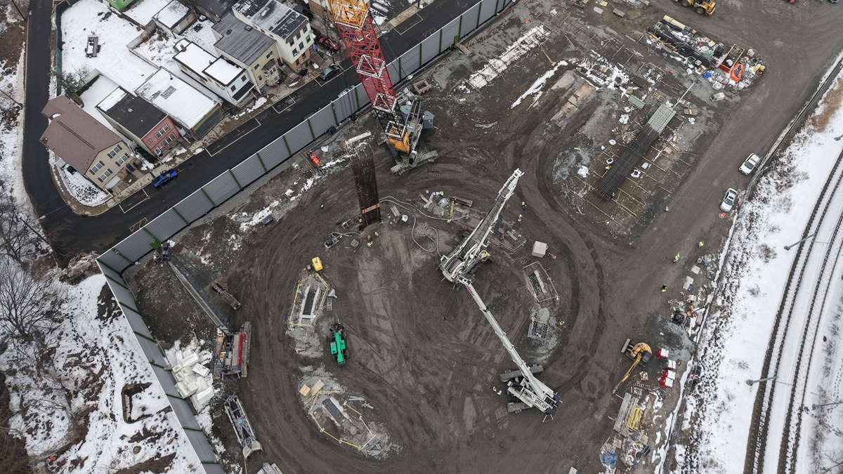
Figure 2. Tunnel shaft dewatered with closely spaced ejector wells.

Furthermore, the design process for dewatering does not necessarily depend on the type of system selected and the correct system may not become apparent until design is well underway. The relevant question then is not “How can I best get water out of the well or dewatering device?” but “How, given the geological conditions at the site, can I ensure that groundwater will flow to my dewatering system at a sufficient rate to achieve the drawdown required?” The answer to this question generally requires a good understanding of the aquifer’s properties, particularly hydraulic conductivity, and the geometry of the aquifer relative to the project.
Hydraulic Conductivity
Hydraulic conductivity is an intrinsic property of the aquifer that measures how readily it will transmit water. Aquifers of lower hydraulic conductivity require pumping relatively small amounts of water to achieve a unit decline in head but individual wells will a have small area of influence, meaning they must be spaced close together. By contrast, higher hydraulic conductivity aquifers require a greater flow but may be spaced further apart.
This presents a problem in terms of defining a baseline condition. Traditionally, flow rate is taken as a proxy for dewatering difficulty and, all else being equal, higher hydraulic conductivity corresponds to hig

Figure 3. Excavation dewatered using widely spaced deep wells.
her flow rate. Therefore, if a certain value of hydraulic conductivity is given as the baseline then the more onerous condition is assumed to be the case where the actual conductivity is higher than the baseline. This is true to the extent that a higher hydraulic conductivity will require mechanical upgrades to the dewatering system, i.e. bigger pumps, piping and electrical systems. However, given the information presented above, a scenario where the hydraulic conductivity is lower than the baseline value could require more dewatering devices owing to the steeper shape of the drawdown curves. This gives the counterintuitive result that a more onerous condition (for which the contractor is presumably entitled to additional fees or schedule relief) could occur for hydraulic conductivity values both above and below the baseline. Figure 2 shows a tunnel shaft in a low hydraulic conductivity aquifer dewatered with tightly spaced low flow devices. Figure 3 shows an excavation dewatered with a high flow system of widely spaced deep wells.
RELATED: Ground Improvement for Groundwater Control

Figure 4. Excavation in a thick aquifer.
Aquifer Thickness
A similar and related issue concerns the depth to the bottom of the aquifer. All else being equal, a thicker aquifer with a deeper bottom will be more transmissive, and require a higher flow to dewater, than a thin aquifer. If we again take flow rate as an indicator of dewatering difficulty, then a thicker aquifer should be regarded as the more onerous condition. However, a thinner aquifer, while being less transmissive, may well present the more challenging dewatering scenario. In Figure 4, the permeable soil extends well below the excavation bottom. This allows a system of relatively few widely spaced wells to have enough well/aquifer contact area to pump the required flow. In Figure 5, however, the excavation extends right down into the impermeable soil, requiring the water to be drawn down as closely as possible to the clay. This necessitates many devices installed on close centers since each device will have very limited contact area with the saturated portion of the aquifer.
Therefore, we once again have a situation where the more difficult and costly dewatering scenario corresponds to a lower, not higher, than expected flow rate. This situation is known to dewatering practitioners as “the interface condition” and is easily the most common source of dewatering disputes.
A Suggestion for Moving Forward

Figure 5. Excavation in a thin aquifer.
As many readers will know, the purpose of a geotechnical baseline report is to streamline the claims process by avoiding disputes. However, the ambiguity described above could lead to disagreements between the parties as to whether or not the actual conditions on the project are more onerous than the baseline conditions.
Therefore, in the case of hydraulic conductivity, we suggest that it is good practice to give a range of values rather than a specific value, and have the contractor be responsible for all conditions within the range but be compensated if the true value falls outside of that range.
The practice of baselining a range as opposed to a specific value seems to be more and more common lately. However, it is undercut by the likelihood that it is driven more by uncertainty about the true value of conductivity rather than the rationale outlined above, and by the fact that the ranges given are typically too large (i.e. two to three orders of magnitude) to be practical. An alternative to this could be to baseline a range of flow rates in lieu of hydraulic conductivity.
The depth to the bottom of the aquifer (or aquifers) is generally much better defined than hydraulic conductivity and can be interpreted directly from boring logs. However, when uncertainty exists because borings are spaced too far apart or because borings did not extend deep enough to reach the bottom of the aquifer, we must bear in mind that a more onerous condition may be lurking below.
The suggestions given above will certainly not eliminate all dewatering disputes. Reasonable and competent practitioners may still disagree on analysis or methods of design. However, if we keep the foregoing in mind we can at least all begin from the same frame of reference.
Gregory M. Landry, P.E., is Chief Dewatering Engineer for specialty geotechnical contractor Moretrench.
RELATED: In Underground Construction, the Sum of the Parts Is Greater Than the Whole

Comments are closed here.