Ground Improvements for the SR 99 Bored Tunnel

Due to the nature of the soft, saturated, unstable soils, which included large volumes of undocumented organic fill and abandoned timber pile foundations, ground improvement was required in critical areas to mitigate tunneling risks. However, due to the unique nature of this project, a standard ground improvement program would not suffice. Many additional factors needed to be considered to mitigate tunneling risk specific to the conditions at hand. One of the main concerns was to contain all horizontal ground influences where the tunnel alignment parallels the active portion of the Alaskan Way Viaduct (current SR 99). The aged viaduct is to remain active during tunnel construction and has been operating in a significantly weakened state since the 2001 Nisqually Earthquake.

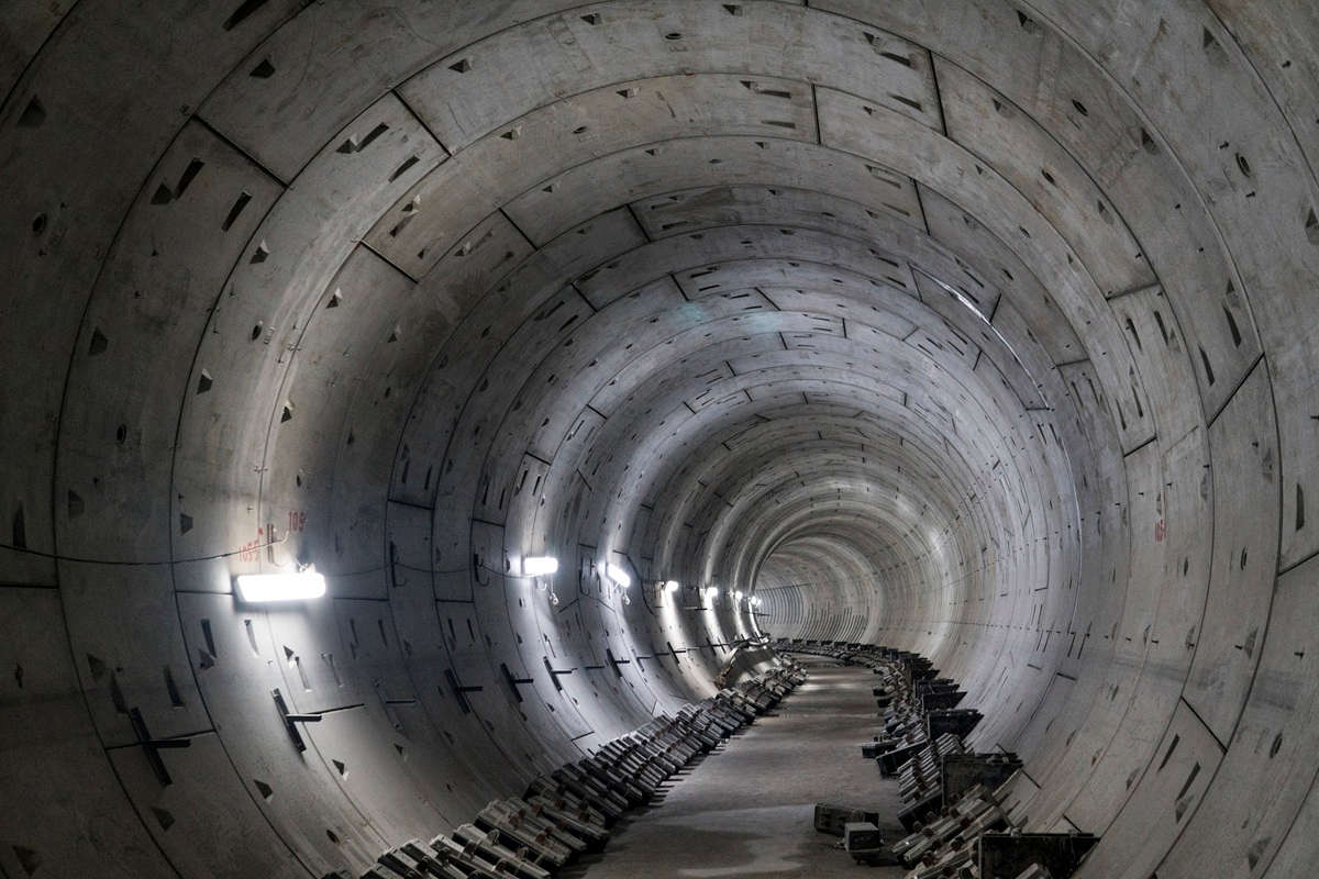
After the TBM leaves the first jet grouted “safe haven” box, it will pass underneath a continuous structural buoyancy slab, which is supported by 5-ft diameter reinforced tangent piles tied together by cap beams. Similar to the first safe haven, the tangent piles extend to a 10-ft depth below the tunnel invert and all soft soils within the tunnel box are improved with jet grouting. The concrete slab will eliminate the potential for uplift. Conversely, to control settlements due to ground loss, the jet grouted “columns” will act as springs to transfer any loads from settlement effects or TBM buoyancy issues. During the excavation of the first 400 ft under the slab, all TBM parameters are to be fully tested since all adverse effects will be confined to the “box.” Potential ground losses or over pressurization will be controlled through block-out casings located every 50 ft along the tunnel centerline.

Secant pile headwalls and containment walls were all constructed with the assistance of guide walls. Concrete guide walls were installed to assist in maintaining pile verticality to ensure proper overlap and continuity between piles, thus providing a continuous wall throughout its depth. The use of guide walls is always desired when striving for the best quality product. Secant piles reached depths of up to 138 ft and were drilled and poured in very difficult ground conditions. The loose or soft ground conditions within the upper 50 to 60 ft provided very little lateral support to the drill casing. Moreover, the piles were required to be drilled within the designed horizontal tolerance (plus/minus 6 in.) throughout its depth while encountering obstructions that ranged from steel piles to buried nests of stacked lumber.
The cased drilling technique was used due to pile length and difficult ground conditions. Temporary casing offers a stable excavation for the full length of each drilled pile. The fully cased drilling method also provided a very rigid drilling system that assisted in maintaining vertical alignment within soft soils while overcoming buried obstructions of which many were problematical. When coupled with the support of the at-grade guide wall, the combined drilling system yields a high-quality product under very restrictive tolerances.
Three rows of continuous secant piles were installed at the first two safe haven headwalls. Five-ft diameter secants were placed on 4-ft centers. As expected, drilling obstructions were routinely encountered and overcome by means of sophisticated drilling tools and modern drilling machines. A pair of Bauer BG50 rotary top drive machines regularly drilled through concrete filled steel piling, timber piles, various nested layers of timber ties and decking or other opposing debris without interrupting the critical primary/secondary secant pile installation sequence. With the BG50’s total operational weight greater than 260 metric tons and rotary drive torque of 500 kNm, all obstructions were easily overcome. To assist with the critical schedule, one BG40 with a torque multiplier was utilized to assist with the work load alongside the two BG50s. Two additional BG40s without torque multipliers worked on less demanding areas of the excavation or tunnel alignment installing tangent piles or primary piles of the secant wall sequence.
Over 400 jet grout columns with diameters ranging from 7.5 ft to 11.5 ft were used to remediate the heavily debris-laden soft soils within the upper reaches of the tunnel horizon from the excavation portal to the second safe haven, about 450 ft down the tunnel alignment. Bound by secant walls, the jet grouting infill for the tunnel-in-a-box ground improvement system was performed using Malcolm’s MEGA-Jet Grouting system. The high-energy double/triple fluid jetting system was limited by the high organic content of the ground treatment zone. The basis of jet grouting is founded on soil erodibility and use of the in-situ soils as the aggregate for the soilcrete product. Consequently, the high organic content limited jet grout column performance in terms of physical geometry and also in terms of strength. Similarly, the construction installation process would be impacted by relic timber piles that can cause shadowing effects by shielding the jetting energy. Consideration also has to be given to the extremely soft deposits of mill sawdust that would permit increased erosional radii well beyond the initial design intent. These limitations were incorporated into a conservative initial design approach that was verified with a test program and subsequent QA testing that was front loaded on the construction schedule.
Achieving jet grout column strength, diameter and continuity were not the only challenges. The greatest challenge for this particular scope of work was verification of the installed product. The highly variable ground conditions would ultimately result in highly variable strength and composition of the installed soilcrete. Strength results obtained from in-situ wet grab samples did reveal a vast range of unconfined compressive strengths, which directly correlated to a wide range of soilcrete unit weights. Physical investigation by coring would only yield sporadic feedback due to a limited sample recovery rate. Repeated attempts to obtain cores at an acceptable recovery rate, when within the highly organic deposits that were randomly laced with coarse gravels, proved fruitless. As was the case many times, multiple sources of data would be needed to fully understand the in-situ conditions and formulate a proper assessment. Data was collected from the limited core recovery, continuous standard penetration test (SPT) profiling adjacent to cored holes, wet grab sampling and downhole video logging. Moreover, the staged excavation of the buoyancy slab would uncover the entire top surface of the jet grout block for visual assessment.
The third TBM safe haven is strategically located just prior to the tunnel alignment crossing beneath the active Alaskan Way Viaduct to allow for any final adjustments prior to this critical juncture. At this point, the tunnel has driven downward to provide about 85 ft of overburden and mining is entirely within very dense or very stiff till and till like soils. The ground conditions were not receptive to jet grouting methods for construction of a solid ground stabilized block. Subsequently, a closed block of 3.3 ft (1m) diameter drilled tangent piles were installed. The confined and untreated limited volume of soil between the tangent piles was later treated with jet grouting to provide a solid/stable block of ground with a global permeability of less than 3.3×10⁻⁸ ft/sec.
Tunnel boring through this critical phase of the project is on track to be completed in late 2013. The project is expected to be completed and open to traffic late 2015, leading to the eventual demolition of the Alaskan Way Viaduct and turning a new page for Seattle’s downtown waterfront.
Richard Hanke, PEng, is with Malcolm Drilling Co. Inc., Kent, Wash., and Tony Stirbys, LEG, is with Seattle Tunnel Partners.
Comments are closed here.