Tunnel Lining Design, Part 2: Analysis Considerations
By Gary Brierley, Joseph Klein, and Randall W. Poston
[EDITOR’S NOTE: This is Part 2 of a two-part series that originally appeared in Concrete International, which is published by the American Concrete Institute. It is being reprinted with permission. Web: concreteinternational.com.]
This article is Part 2 of a two-part examination of the design and analysis of curved tunnel linings. As discussed in Part 11,beneficial interactions between the tunnel lining and the surrounding ground ensure that tunnel linings are not typically exposed to intense internal or external loading conditions. Analysis models that do not consider these beneficial interactions will overestimate demands and result in unnecessarily conservative designs. Current ACI CODE-318-19(22)2 provisions do not allow the licensed design professional to take full advantage of these beneficial interactions, especially in the case of unreinforced tunnel linings. Accordingly, the authors recommend increasing current ACI CODE-318-19(22) resistance (ϕ) factors for unreinforced tunnel linings to match their expected behavior.
Background
In Part 1 of this article, it was established that concrete tunnel linings possess unique geometric attributes that allow independent and equally beneficial ground/lining interactions. Most final tunnel linings are designed to accomplish long-term functional, serviceability, and durability requirements, not because they will be subjected to intense internal or external loading conditions. Once a final lining has been designed based on these considerations, that lining can be analyzed to make certain that it has sufficient structural capacity to safely support whatever ground loads are expected to take place following construction.
There is an enormous amount of confusion and over-conservatism in the design of concrete tunnel linings. The primary purpose of this article is to show how curved tunnel linings can be designed and analyzed in a reasonable and rational manner that is consistent with tunnel lining behavior. Part 1 of this article covered design considerations and a brief history of tunnel linings. This second part presents recommendations for tunnel analysis and proposes changes to ACI capacity calculations to take advantage of beneficial tunnel lining behavior.
Determining Tunnel Lining Demands
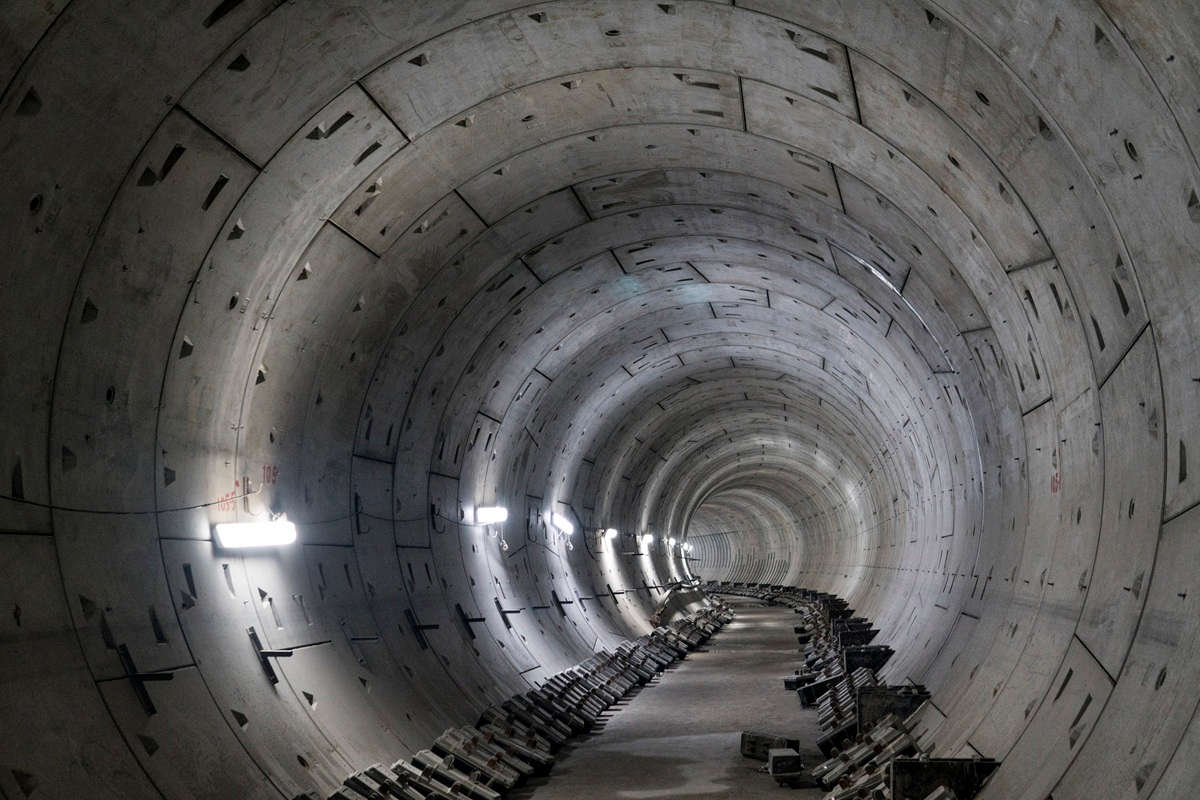
Curved tunnel structures work together with the surrounding ground to create an inherently stable structure. The surrounding ground confines and restrains the tunnel lining both radially and circumferentially and creates a composite structure that is sensitive primarily to strain deformations, not stress concentrations. Specifically, if ground loads cause a portion of the tunnel lining to deform, that deformation will cause the ground load to be redistributed back into the ground, where it can be supported by adjacent portions of the tunnel lining. Deformations within the curved tunnel lining itself also result in a reduction in the moments that can be imposed on the lining and an increase in lining compressive stresses, both of which are highly beneficial for structural integrity.
Ground/lining interaction
One of the most comprehensive investigations of the ground/lining interaction phenomenon was performed in the early 1980s by the University of Illinois for the U.S. Urban Mass Transportation Administration. As stated in the final report:
“The objective of the work was to provide recommendations for structural design of final concrete linings for tunnels and underground facilities for mass transportation use, that include ultimate strength design and ground-lining interaction concepts, and to improve the understanding of lining behavior as it interacts with the ground3.”
The investigation included:
- Testing of full-scale, instrumented tunnel linings to failure, to discover exactly how a curved tunnel lining interacts with the surrounding ground;
- Interviews with tunnel designers and contractors, to establish design practices in use at that time; and
- Computer modeling, to perform parametric studies on a wide variety of ground loading and ground restraint mechanisms.
It is beyond the scope of this article to describe all the details of that investigation; however, suffice it to say that it provided the basic framework for accurate structural modeling of tunnels.
Curved tunnel linings
A section of a curved tunnel lining can be modeled as a series of beam elements centered on chords of the lining arc. Radial and tangential springs at each node simulate the stiffness of the surrounding ground. The radial springs simulate the compressive confinement provided by the ground and are modeled as compression-only springs. The circumferential springs simulate the frictional and/or shearing resistance provided by the surrounding ground and are usually set to a stiffness of one-half to one-third of the radial springs. Once this model is established, ground loads are applied, and the structural demands are computed.
The following observations are based on computer simulations for both rock and soil:
- A rock mass with an unconfined compressive strength of at least 1,000 psi will have a huge, positive impact on reducing the amount of moment that can be imposed on a tunnel lining. In particular, the circumferential restraint will greatly diminish the moments induced in the lining as compared to a free-standing structure. It is practically impossible to fail such a lining grouted into contact with a rock mass, unless that lining is subjected to high swelling or squeezing pressures or seismically induced ground deformations. In the former case, the lining will fail in shear, and in the latter case, the lining will crack;
- For tunnels in soil, ground pressures and ground restraints vary widely depending on the soil type. In general, ground pressures in soil are more uniform as compared to rock and provide both vertical and horizontal load components. Together with groundwater loading, these pressures induce compressive stresses into the lining that are beneficial for resisting tensile stresses caused by lining moments. Various forms of clay deposits may be able to apply swelling or squeezing pressures, and seismically induced deformations in soil can be more severe, up to and including soil liquefaction. Accordingly, structural capacities for soil tunnel linings must be more robust as compared to rock tunnels, meaning that soil tunnel linings usually consist of some type of precast concrete pipe, steel pipe, or cast-in-place reinforced concrete lining. Soil tunnel linings must also be firmly grouted against the ground to take maximum advantage of the ground/lining interaction provided by even the weakest of soils; and
- All initial supports, for both rock and soil tunnels, create a permanent decrease in ground load intensity and an increase in ground/lining interaction. Once ground deformations are stabilized with the help of initial supports, this stabilization is permanent unless and until additional ground deformations are allowed to occur, which is not possible once the final lining is installed and grouted against the ground. As demonstrated by thousands of tunnels constructed throughout the world, the ground itself, as restrained by the initial support and supported by the final lining, is almost always able to provide a long-term and highly stable composite structure. In fact, the primary function of the final lining is to confine and support the ground so that the ground is forced to support itself.
Additional considerations
To finalize this discussion of ground/lining interaction, it is necessary to discuss a few miscellaneous aspects of this phenomenon:
- Flat surfaces—Sometimes it is necessary to create a flat surface underground. Flat surfaces require more robust initial supports to minimize the ground loads impacting the lining and must be reinforced to resist the tensile stresses that may develop on the inside surface of the lining. If the above is accomplished, most of the ground forces exerted on the lining will still be carried by arch action within the ground itself;
- Fault crossings—Occasionally, a tunnel will cross an active fault. The only way to prevent damage to the tunnel lining in this situation is to create an opening around the tunnel large enough to accommodate any anticipated movement along the fault. It is simply not possible to make a tunnel lining strong enough to resist fault deformations;
- Internal pressure—Tunnel linings exposed to large internal pressures must be designed to withstand those pressures unless the tunnel is located at sufficient depth below the ground surface (usually in rock). Shallow, pressurized tunnels are typically lined with pipe specifically designed to resist that pressure. Hydroelectric power projects represent a particularly severe example of the design issues associated with pressurized tunnels;
- Waterproofing membranes—Transportation tunnels frequently require limiting or preventing water leakage. In general, the best method to accomplish that goal is to install a fabric or spray-on waterproofing membrane prior to final lining installation. This membrane creates a slip surface around the tunnel lining, which reduces the ability of the final lining to minimize moments and results in an increased tendency for shrinkage cracks. For rock tunnels, it is necessary to install a shotcrete “smoothing surface” for the membrane, which can be used as an initial support prior to installation of the membrane. For soil tunnels, the final lining must be reinforced to resist the anticipated shrinkage and flexural stresses. One of the best methods to reduce shrinkage cracking in soil tunnels is to reinforce the lining with fibers instead of reinforcing bars;
- Intersections and penetrations—Tunnel intersections and penetrations create complex, three-dimensional stress distributions within the ground. In most cases, the strains created by those stress distributions can still be controlled by the installation of adequate initial support, but it is almost impossible to convince structural engineers not to install reinforcing steel in the vicinity of these types of intersections and penetrations;
- In-place stress—Some rock formations are subjected to high levels of horizontal stress that can cause spalling around the perimeter of the excavation. The magnitude and intensity of this phenomenon can be quite severe depending on the amount of stress and the orientation of the stress field relative to the tunnel alignment. For example, if the stress field is oriented east-west and the tunnel is oriented north-south, rock fracturing will occur in the crown of the tunnel, and it will need to be controlled by rock bolts and wire mesh. If the rock is strong and the stress is great, dangerous rock “explosions” are also possible, and the engineer should also consider consolidation grouting of the broken rock trapped around the perimeter of the tunnel following erection of the final lining; and
- Corrugated metal linings—In general, these linings are too thin and flexible to withstand any moment and must be uniformly backfilled and restrained by contact grouting. Once installed, however, these linings can support all imposed ground loads by thrust alone and provide an ideal example of the power of arch action within the surrounding ground.
Determining Tunnel Lining Capacity
Current code provisions
It is quite common for contract documents to reference ACI CODE-318 and ACI CODE-350 provisions with respect to the “design” of tunnel linings, but those code provisions relate exclusively to free-standing, above-ground structures and not arched, underground structures constructed within and restrained by the ground. This results in unduly conservative design assumptions for unreinforced concrete tunnel linings in particular, which will have similar structural capacities as compared to above-ground reinforced linings3.
ACI CODE-350 is often considered the applicable code for tunnels, given their frequent use in environmental applications. However, curved tunnel lining structures are only partially covered by ACI CODE-350. Section 1.1.5 of ACI CODE-350-20 states: “For special structures such as arches, bins and silos, blast-resistant structures, and chimneys, provisions of this Code shall govern where applicable4“. In addition, meeting the requirements of ACI CODE-350 is likely not necessary due to the low structural demands for a curved tunnel lining in contact with the surrounding ground.
For a reinforced tunnel liner, ACI CODE-318-19(22) and ACI CODE-350-20 require the same capacity calculation assumptions (that is, concrete crushing compressive strain limit of 0.003), so an identical section will result in an identical capacity using either code. However, the authors would generally recommend using ACI CODE-318 instead of ACI CODE-350 to design tunnel lining structures.
The primary difference between ACI CODE-318 and CODE-350 is in how the structure is detailed. For example, ACI CODE-350 specifies higher shrinkage and temperature steel requirements than ACI CODE-318 due to the potentially adverse effects of cracking for environmental structures. Discussion of how to account for all possible nonstructural considerations is beyond the scope of this article, but tunnel lining designers should consider detailing in accordance with ACI CODE-350 if serviceability concerns are particularly important. If the designer does elect to use plain concrete, the designer must also consider the tensile stresses caused by creep, shrinkage, and temperature effects.
Whether cast-in-place, precast, or shotcrete, curved tunnel linings are members subject to combined flexural and axial load. As such, structural capacity checks are conducted using interaction diagrams. For plain concrete, the interaction diagram is calculated using Section 14.5.4 of ACI CODE-318-19(22), where the designer can take the length of compression member as zero because the surrounding ground will prevent buckling. For reinforced concrete, the interaction diagram is calculated sectionally according to Sections 22.2 and 22.4 of ACI CODE-318-19(22) and Sections 10.2 and 10.3 of ACI CODE-350-20. The maximum axial strength (Table 22.4.2.1 of ACI CODE-318-19(22) and Section 10.3.6 of ACI CODE-350-20) can conservatively be taken as the minimum calculated value. However, it could be argued that the maximum calculated value is appropriate because the reduction in maximum axial strength is intended to account for accidental eccentricity, and the surrounding ground will prevent the tunnel lining from buckling.
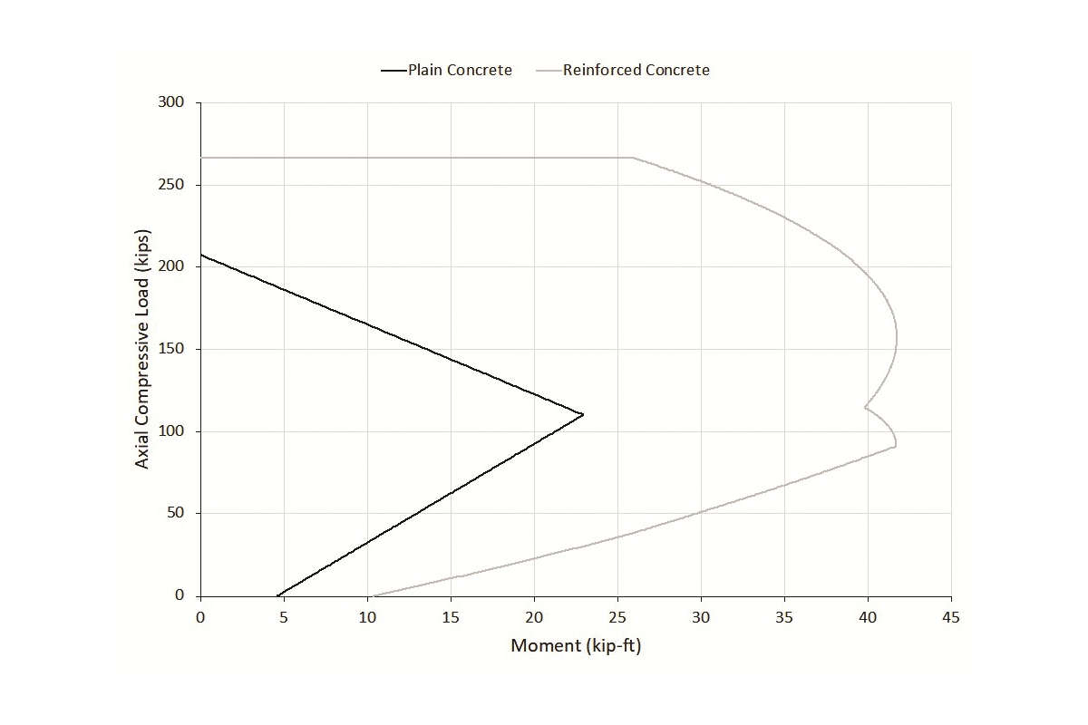
Fig. 1 provides example moment-axial interaction diagrams (computed in accordance with ACI CODE-318-19(22)) for plain and reinforced concrete tunnel lining sections, assuming a 12 x 12 in. concrete section with a concrete compressive strength (fcʹ) of 4,000 psi. The reinforced section contains No. 4 bars at 12 in. on-center on each face with 3 in. of concrete cover.
To determine the adequacy of the design, the combined flexural and axial demands are plotted. If these demands fall within the interaction diagram failure envelope, the tunnel lining capacity is sufficient to resist the applied loads. Jacked pipes also require the designer to check the effects of jacking forces on the pipe section—this topic is not discussed in this article.
ϕ Factors
As shown in Fig. 1, ACI CODE-318-19(22) provisions suggest that an unreinforced section has a much lower capacity than a similarly shaped reinforced section for all combinations of axial compression and moment. However, much of this disparity is due to the specified strength reduction factors (ϕ factors). According to Table 21.2.1 of ACI CODE-318-19(22), designers must apply a ϕ factor of 0.6 for unreinforced sections and a ϕ factor ranging from 0.65 to 0.9 for reinforced sections, depending on the maximum tensile strain in the reinforcement. The purpose of these variable ϕ factors is to reflect the predictability of a particular failure mode and the potential consequences of that failure mode. Accordingly, failure mechanisms such as shear receive lower ϕ factors than failure modes such as tension-controlled flexure.
Variable ϕ factors are an integral feature of ACI CODE-318 provisions, and thus, it makes sense to have a different ϕ factor for unreinforced tunnel linings as compared to, for example, unreinforced, above-ground walls. Unlike other plain concrete structures, unreinforced tunnel linings have similar structural capacities to reinforced linings based on the large-scale testing program by Paul et al.3 This increase in unreinforced capacity is due to the confinement of the surrounding ground, which prevents the tunnel lining from buckling. Accordingly, the authors recommend increasing the ACI CODE-318-19(22)-specified ϕ factors for curved, unreinforced tunnel linings in direct contact with the ground.
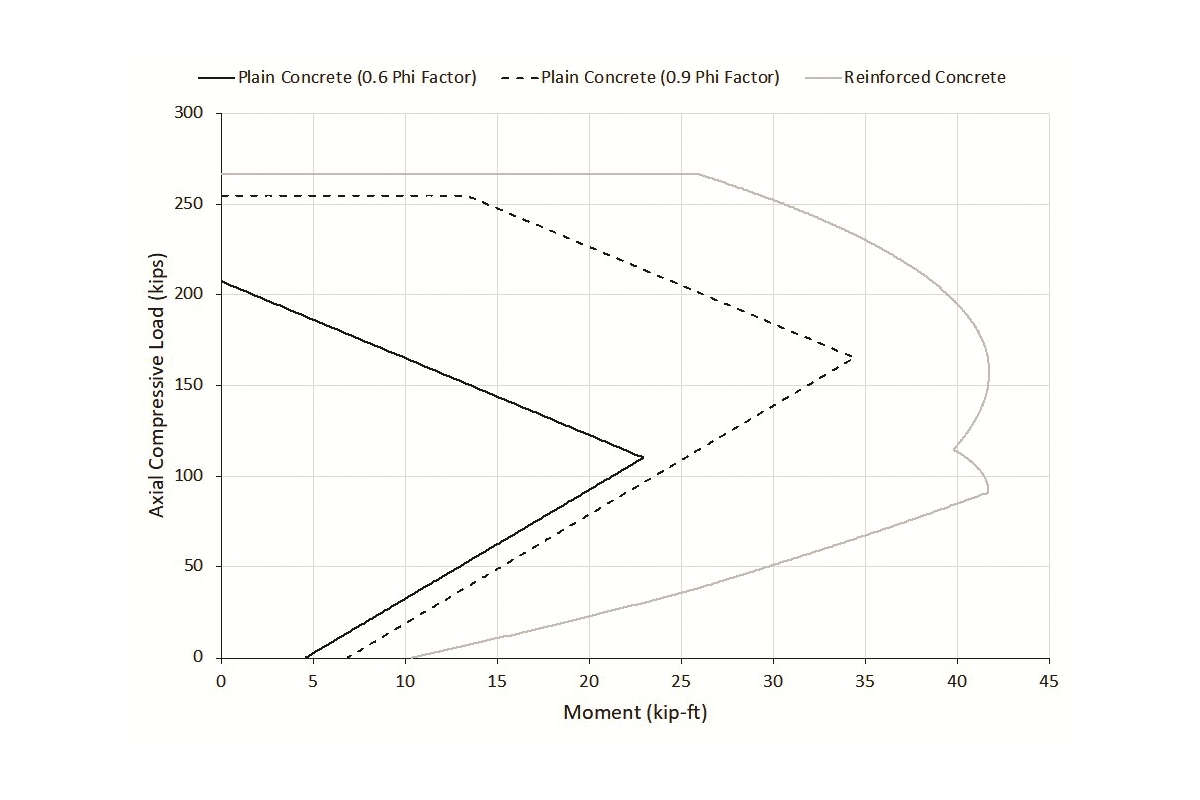
The goal of increasing ϕ factors for unreinforced tunnel linings is to match the expected behavior more closely, namely, a similar capacity whether a tunnel lining is unreinforced or reinforced. As shown in Fig. 2, this goal can be achieved if the ϕ factor for unreinforced tunnel liners is increased to 0.9, the maximum ϕ factor for the reinforced case. An unreinforced section should not have a higher computed capacity than a reinforced section, so the maximum axial compressive force should be limited to the value given in Table 22.4.2.1 of ACI CODE-318-19(22), similar to what is done for reinforced sections. The authors recommend using a ϕ factor of 0.65 when calculating this limiting capacity—a higher ϕ factor on this limiting value results in capacities greater than the reinforced case. The recommended limit on maximum axial compressive force is also shown in Fig. 2.
While the authors believe that the recommended increase in ϕ factors is appropriate, code changes typically require extensive study and consensus-based acceptance in the industry. Acceptance of the ability of unreinforced tunnel linings to safely carry their expected design loads is already present within the tunneling industry, but this acceptance is not reflected in the current ACI code documents. Even if the authors’ recommended ϕ factor adjustments are not adopted, current ACI code provisions need to be reexamined for unreinforced tunnel linings. The current provisions are unduly conservative, result in significant material waste, and poorly reflect the inherent safety of tunnel linings placed in direct contact with the surrounding ground.
Summary
Final tunnel linings are typically designed to accomplish long-term functional, serviceability, and durability requirements, not because they are subjected to intense internal or external loading conditions. Their curved geometry, coupled with ground/lining interactions, results in linings that have much lower demands and much higher capacities than generally accounted for when designing strictly in accordance with ACI code documents. Consequently, tunnel linings may be “overdesigned” by structural engineers who have no background or experience dealing with curved, arched structures erected within and restrained by the ground.
Many designers ignore the adequacy of unreinforced tunnel linings, despite the existence of thousands of unreinforced tunnel linings throughout the world, including some dating back hundreds of years. Unreinforced concrete in direct contact with the ground is a viable support mechanism for tunnel openings and should not be discounted. The inclusion of large amounts of reinforcing steel in a tunnel lining is almost never required and adds considerably to difficulty, cost, and time required to construct that lining with little to no added benefit. In fact, the inclusion of steel reinforcement in a tunnel lining could detract from its service life due to, for example, corrosion.
Current ACI code requirements were developed primarily for application to above-ground, free-standing structures, which inherently behave differently from tunnel linings. Variable ϕ factors are an integral feature of ACI CODE-318 provisions, and the authors believe that it is appropriate to increase the ϕ factors for unreinforced tunnel linings to take advantage of beneficial tunnel lining behavior.
References
1. Brierley, G.; Klein, J.; and Poston, R.W., “Tunnel Lining Design, Part 1: Design Considerations,” Concrete International, V. 45, No. 6, June 2023, pp. 43-47, and TBM: Tunnel Business Magazine, V. 28, No. 4, August 2025, pp. 26-29.
2. ACI Committee 318, “Building Code Requirements for Structural Concrete and Commentary (ACI CODE-318-19) (Reapproved 2022),” American Concrete Institute, Farmington Hills, MI, 2019, 624 pp.
3. Paul, S.L.; Hendron, A.J.; Cording, E.J.; Sgouros, G.E.; and Saha, P.K., “Design Recommendations for Concrete Tunnel Linings, Volume II: Summary of Research and Proposed Recommendations,” Report No. UMTA-MA-06-0l00-83-3, U.S. Department of Transportation, Urban Mass Transportation Administration, Washington, DC, Nov. 1983, 176 pp.
4. ACI Committee 350, “Code Requirements for Environmental Engineering Concrete Structures and Commentary (ACI CODE-350-20),” American Concrete Institute, Farmington Hills, MI, 2021, 549 pp.
About the Authors
Gary Brierley has more than 50 years of experience relating to the design and construction of tunneling projects. His doctoral dissertation addressed the structural performance of the tunnel lining for Dupont Circle Metro Station in Washington, DC, USA, and he has authored more than 200 papers and articles on underground openings. In 2014, he received a Distinguished Alumnus Award from the University of Illinois. He received his BS in civil engineering from Tufts University, Medford, MA, USA, in 1968, and his MS and PhD from the University of Illinois at Urbana-Champaign, Urbana, IL, USA, in 1970 and 1975, respectively.
ACI member Joseph Klein is a Senior Engineer with Pivot Engineers in Austin, TX, USA, and his professional experience is focused on the evaluation and repair of concrete structures. He is a member of ACI Committees 132, Responsibility in Concrete Construction; 348, Structural Reliability and Safety; 437, Strength Evaluation of Existing Concrete Structures; and 444, Structural Health Monitoring. He received his BS and MS in civil engineering from The University of Texas at Austin, Austin, TX, in 2013 and 2015, respectively.
Randall W. Poston, FACI and ACI Past President, is a Senior Principal with Pivot Engineers, Austin, TX. For the past 37 years, he has been engaged in the evaluation, repair, and strengthening of hundreds of structures. He is Chair of the ACI Standards Board and is a member of ACI Committee 318, Structural Concrete Building Code, of which he was Chair during the 2014 Code cycle; and ACI Subcommittees 318-D, Members, and 318-N, Sustainability. Poston received his BS, MS, and PhD in civil engineering from The University of Texas at Austin, Austin, TX.
Comments are closed here.