Tunnel Lining Design, Part 1: Design Considerations
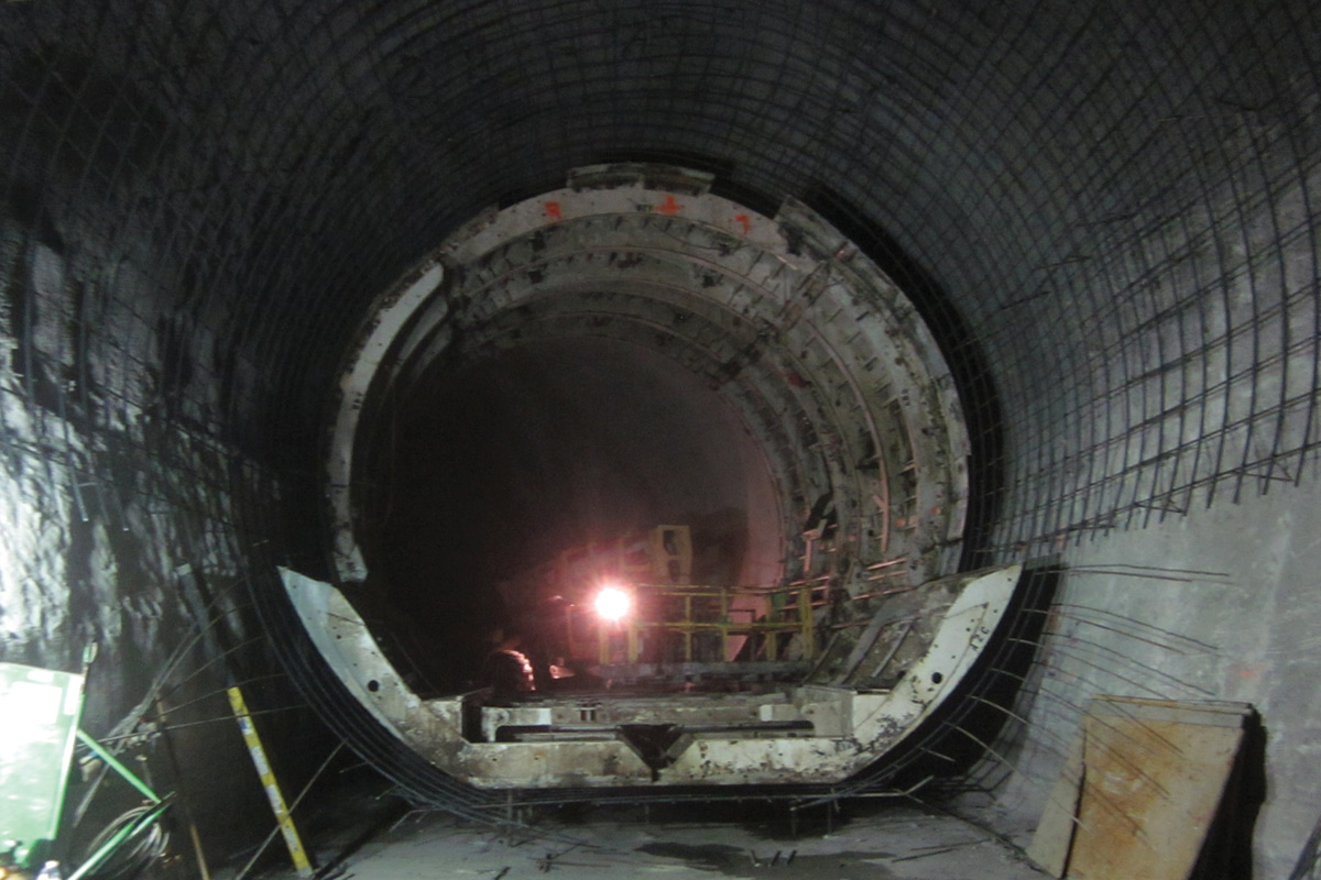
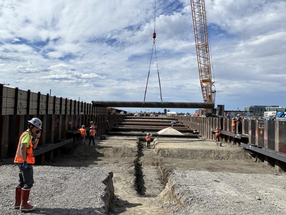
Fig. 1 – Curved tunnel lining
[EDITOR’S NOTE: This is Part 1 of a two-part series that originally appeared in Concrete International, which is published by the American Concrete Institute. It is being reprinted with permission. Web: concreteinternational.com.]
By Gary Brierley, Joseph Klein, and Randall W. Poston
Current requirements of ACI CODE-318-19(22), “Building Code Requirements for Structural Concrete,”1 and ACI CODE-350-20, “Code Requirements for Environmental Engineering Structures,”2 relate almost exclusively to aboveground structures. However, aboveground structures are fundamentally different from tunnel linings, which are typically curved structures placed in direct contact with and restrained by the surrounding ground. This difference can lead to an enormous amount of confusion and overconservatism in the design of tunnel linings. For this article, “ground” is used to collectively refer to both soil and rock. Differences between soil and rock tunnels are discussed in more detail in Part 2.
The primary purpose of this article is to show how curved tunnel linings can be designed and analyzed in a reasonable and rational manner that is consistent with tunnel lining behavior. Part 1 presents tunnel lining design considerations and a brief history of tunnel linings. Part 2 will offer recommendations for tunnel analysis and proposes changes to ACI capacity calculations to take advantage of beneficial tunnel lining behavior.
Moment/Thrust and Ground/Lining Interactions
Curved tunnel linings benefit from a process known as moment/thrust interaction, whereby the structure can generate moments and thrusts simultaneously, creating a high degree of structural capacity for all types of concrete cross sections. For example, everyone has seen pictures of curved, arched structures that have survived for hundreds of years without the benefit of any steel reinforcement.
A curved concrete structure in direct contact with the ground also benefits from two independent and equally beneficial ground/lining interactions: arch action and movement restraint. In this context, arch action is the term used for the tunnel lining and the surrounding ground acting together as a composite structure, meaning that the loads imposed on the lining by the surrounding ground can be supported both by the lining and by the ground, depending on the magnitude of strain distribution. For example, if the tunnel lining tends to move in a certain area, the loads imposed on the lining in that area will be redistributed back into and supported by the ground.
Movement restraint refers to the ground’s restraint of the lining, preventing the lining from developing large moments. In an aboveground structure, such as an elevated slab system in a building, the loads imposed on the slab cause the slab to deflect and generate tensile stresses that must be counteracted with reinforcing steel. However, if that slab is placed in direct contact with the ground, the magnitude of moments developed in the slab are virtually nonexistent as compared to elevated slabs. For curved, cast-in-place concrete linings placed in direct contact with the ground, this form of restraint takes place both radially and circumferentially around the entire lining perimeter. In fact, beam/spring and finite element models of ground/lining interaction have shown moment reductions of as much as two orders of magnitude for curved concrete linings in direct contact with a rock mass, which will be discussed further in Part 2.
Due to these beneficial ground/lining interactions, even unreinforced curved concrete tunnel linings generally have the sufficient structural capacity to be perfectly safe and stable. This is the case for almost all ground loading conditions, except for extremely weak ground, squeezing or swelling ground conditions that generate intense ground pressures, seismically induced ground deformations caused by earthquakes, or high-intensity internal fluid pressures, all of which are quite rare for most tunnel linings.
Influence of Functional Requirements on Lining Design
Underground tunnels are used in a vast array of civil infrastructure projects, especially in densely populated urban environments. For example, the following civil facilities may require tunneling:
- Transportation—highways, railroads, subways, and pedestrian;
- Water—water supply, drainage, sewage, and hydroelectric;
- Utilities—gas, electric, water, and communication; and
- Miscellaneous—civil defense, military applications, storage facilities, and wine caves.
To create these tunnels, various design and construction procedures are required to make the ground opening safe and stable. The tunnels must fulfill specific operational and serviceability requirements, and they are typically intended to have a long service life. Consideration must be given to durability, access for maintenance, and the possibility of fire, freezing conditions, and chemical attack, and the tunnel lining is integral to all these considerations.
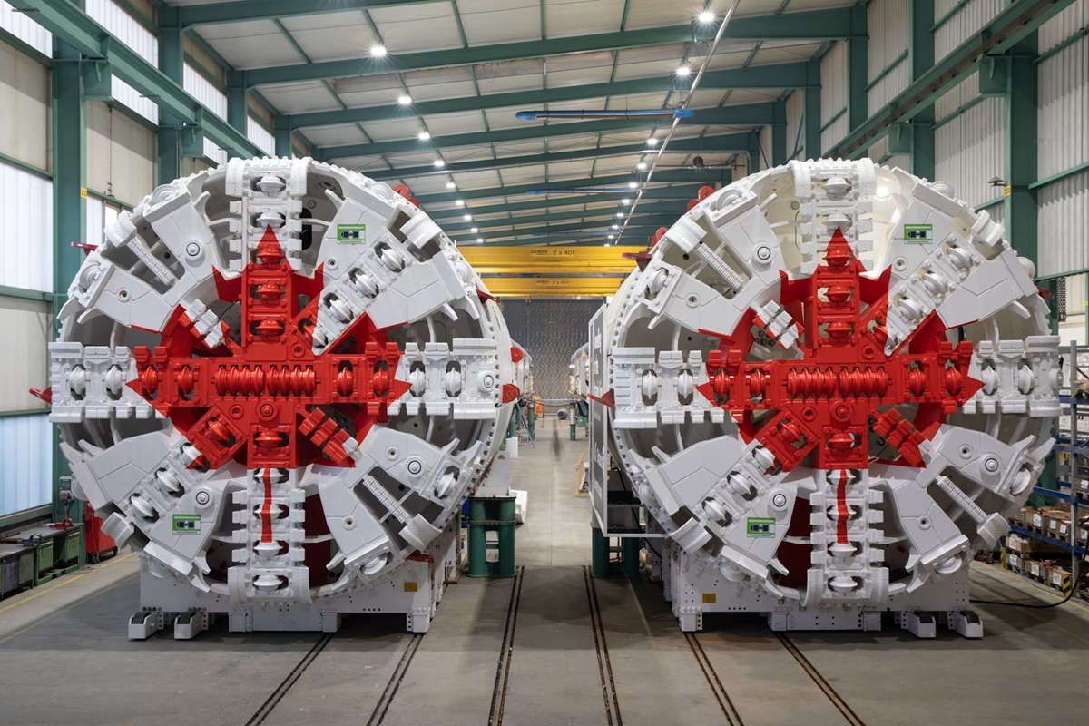
Consideration must also be given to what types of linings can be constructed in the highly confined space associated with many tunnels. Historically, tunnel linings used timber, brick, blocks of rock, plain concrete, cast-iron segments, and steel ribs. Beginning in the 1950s, rock bolts and shotcrete were introduced, followed by the bolted and gasketed precast concrete segmental linings compatible with various types of tunnel boring machines (TBMs). TBMs also increased the daily rate of advance for tunneling projects and dramatically decreased the amount of disturbance caused to the ground, as compared to drilling and blasting with open-face shields.
Lining types
Tunnel linings can be broken down into two basic classifications: one-pass and two-pass linings. There are two basic forms of one-pass tunnel linings: jacked pipe and shotcrete. Pipe jacking, also referred to as micro tunneling, is typically used for tunnels that are less than 10 ft (3 m) in diameter, and several types of pipes have been designed especially for that purpose, including precast concrete segmental linings. The pipe must withstand the jacking forces imposed by the TBM, meaning that the pipe must be either reinforced with or composed of steel. Jacked pipe must be grouted against the ground after installation to provide a stable arched structure that can withstand large external ground loads and both internal and external water pressures. Shotcrete can be used as a one-pass lining in rock or stable soils, such as stiff clay. Following excavation, the shotcrete can be placed in layers as the tunnel advances until the shotcrete is thick enough to serve as the final lining. Shotcrete can be fiber-reinforced to provide additional shrinkage control and structural capacity.
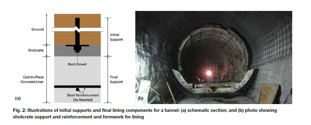
Two-pass linings involve the installation of initial supports (Fig. 1), followed by construction of the final lining. For initial support of soil tunnels, it is common to use steel ribs, wood lagging, and filter fabric. For rock tunnels, initial support can be provided by rock bolts and mesh, shotcrete, and/or steel ribs for the more unstable rock formations. Regardless of the method used, initial supports must create a safe and stable opening that is large enough for construction of the finished facility.
Final linings
Final linings typically consist of either cast-in-place concrete, shotcrete, or pipe. Cast-in-place concrete is the most common lining for tunnels and caverns, and it can be either plain or reinforced with bars, wire mesh, or fibers. In general, the primary function of reinforcement in concrete linings is to control shrinkage cracking during curing, with a modest increase in moment capacity. Shotcrete is just another form of cast-in-place concrete that, once cured, has all the same properties as concrete placed behind a form. Unlike formed concrete tunnel linings, shotcrete does not require backfill grouting to make certain that the lining is in good contact with either the exposed ground or the initial lining.
It is also possible to install pipe into the tunnel, which, once installed, is fully back grouted against either the ground or the initial support. Final linings provided by pipe have many advantages as compared to cast-in-place concrete, including the fact that the pipes are precast using carefully controlled casting procedures. Tunnels intended to be pressurized typically use welded steel pipe.
One of the most important objectives of this article is to establish the concept that the materials and dimensional characteristics of the final lining are mainly established by its functional requirements, not by its structural capacity. For example, it is simply not feasible to place less than 8 in. (203 mm) of concrete between a steel form and the surrounding soil, so those linings are often 10 to 12 in. (254 to 305 mm) thick. Shotcrete linings can be thinner, but the serviceability and durability requirements for most tunnels would require, once again, at least 8 in. of shotcrete for a final lining. Similarly, the installation process for pipe and segmental linings means that they are typically created with high-strength materials and tight tolerances. In other words, the preceding final lining characteristics will be determined by the tunnel’s functional requirements, not by its ability to withstand ground loads.
Modern day tunnel construction practices greatly limit the amount of ground load imposed on the final lining due to minimal disturbance to the ground during excavation, the installation of safe and stable initial linings, or both. Hence, it has become possible to “design” the basic characteristics of the final lining based on its functional requirements and then to “analyze” that lining to make certain that it can safely withstand the ground loadings to which it will be subjected. This process is in contrast with reinforced concrete buildings and environmental structures, wherein design generally follows the analysis process. As previously noted, the dominance of the tunnel’s functional requirements is the case for almost all ground-loading conditions.
Ground Loads for Tunnel Linings
A mind-boggling array of various methods for estimating ground loads caused by tunneling have been developed over the years, but the fact remains that the effects of ground load on the behavior of tunnel linings can be “analyzed” for the final lining once the characteristics of the as-constructed tunnel lining have been determined. Many structural engineers ignore the positive contributions made to lining stability provided by the initial support, but it is a fact that all underground openings must be made both safe and stable prior to installation of the final lining. This changes the ground loads that the final lining must resist.
Arch action
It is a well-established fact that both soil and rock ground loads exhibit “arch action” when an opening is excavated. In essence, the ground surrounding the opening deforms and mobilizes frictional and shear forces that tend to stabilize the ground in the vicinity of the opening. This means that a tunnel excavated at great depth in good-quality rock can be entirely safe and stable without the use of any tunnel lining whatsoever. However, poor-quality rock or soils may require considerable efforts to ensure stability prior to installation of the final lining.
Section I of the 1946 publication, “Rock Tunneling with Steel Supports,” offers an early attempt to document the concept of “arch action.”3 In that treatise, Proctor, White, and Terzaghi provided discussion of various types of rock structures and how those rock structures could impose differing amounts of ground load and/or pressure on a tunnel lining. Karl Terzaghi’s “Introduction to Tunnel Geology” portion of the treatise summarizes the concept of arch action based on the ground type as follows:
“In perfectly or almost perfectly intact rock, no support is required unless popping is encountered. In stratified or moderately jointed but otherwise intact rock, the tunnel support serves its purpose if it is able to sustain a moderate rock load. In crushed rock, the loading conditions are similar to those to be encountered when mining through sand; and in zones of rock decomposition, they are similar to those in tunnels through clay. Tunneling through clay may be very easy or very difficult, depending on the character and degree of compaction of the clay. An equally wide range of conditions is encountered when mining through decomposed rock. The behavior of the worse types of decomposed rock are indicated by the terms squeezing and swelling rock.”
Following an extensive discussion of the mechanics of how rock loads develop during tunnel construction, Terzaghi classified ground conditions with respect to estimating ground loads for tunneling projects, which is referenced even today:
- Intact rock with few joints or cracks;
- Stratified rock with bedding planes;
- Moderately jointed rock;
- Blocky and seamy rock;
- Crushed rock with mostly frictional characteristics;
- Squeezing rock with clay-like properties; and,
- Swelling rock resulting from volumetric expansion.
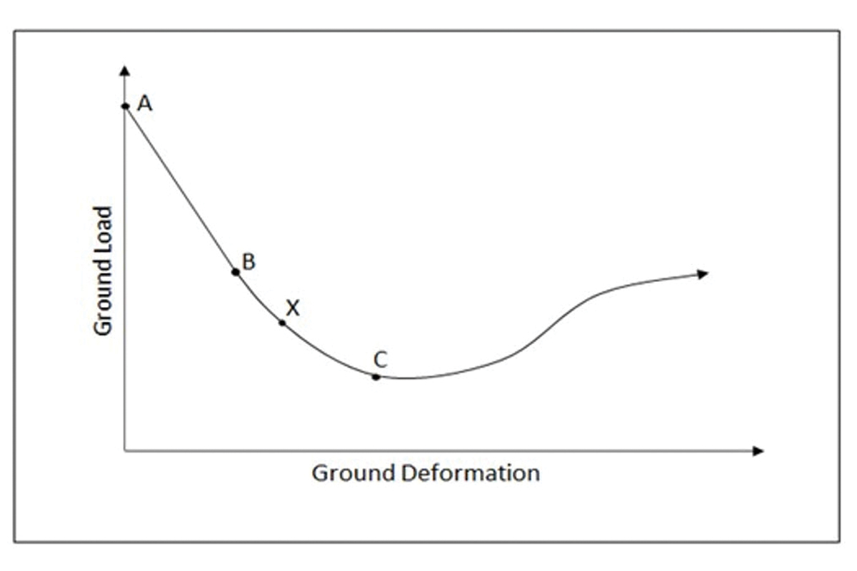
Although Terzaghi’s discussion of ground loading was useful and pertinent for the tunneling methods in use as of 1946, those methods are mostly unrelated to the tunneling methods in use today. Beginning in the 1950s, extensive use of rock bolts and shotcrete revolutionized initial ground support. The use of TBMs and road-headers revolutionized ground excavation by radically reducing the degree of ground disturbance and the amount of ground load that could be mobilized due to tunnel construction. In response, the concept of a ground reaction curve was developed, as shown in Fig. 2.
Point A represents the in-place stress regime in the ground prior to any tunneling. As the tunnel approaches Point A, the ground begins to move in front of the excavation face, thereby distributing the in-place ground stress away from the opening. This stress distribution is approximately elastic until it reaches Point B, where inelastic deformations further reduce ground loads. However, these inelastic deformations may result in a reduction of the ground’s ability to support itself. Beyond Point C, the ground has become destabilized, and the ground load begins to increase. In essence, therefore, initial supports are intended to control ground deformations to somewhere between Points A and C (Point X) by using the wide variety of techniques outlined here:
- For rock—steel ribs, rock bolts, shotcrete, spiling, consolidation grouting, dewatering, and ground freezing; and
- For soil—steel ribs, grouted dowels, shotcrete, forepoling, chemical grouting, jet grouting, dewatering, ground freezing, compressed air, and/or pressurized face TBMs.
Additional factors
The functional requirement of the various forms of initial support listed previously is to produce a safe and stable underground opening inside of which the finished facility can be constructed. The ground stability produced by the initial support is permanent, as any increase in ground load can only occur if the ground is allowed to experience additional deformation, which is not the case once the final lining is installed. In effect, the amount of ground load that will be imposed on the final lining is a function of the amount of ground deformation that takes place during construction. If that ground deformation is stopped by the initial lining, it is not possible for the ground load to increase beyond what was experienced during tunnel construction, with the following exceptions:
Groundwater pressures—Groundwater pressures can be controlled during construction by allowing the ground to drain, by using construction dewatering, and/or using compressed air or a form of pressurized face tunneling. Groundwater pressures will reduce the amount of frictional resistance developed in the ground during construction, but these groundwater pressures will be reimposed following the construction of the final lining. Interestingly, this loading condition is approximately uniform around the perimeter of the tunnel, and unless it is of great magnitude, it is actually beneficial in terms of causing compressive stress in the lining that helps counteract any tensile stress caused by lining moments.
Swelling ground—Swelling is the increase in ground volume caused by highly active clay particles absorbing water. Swelling pressures typically become manageable after small deformations, but not always, and laboratory testing is required to determine the relationship between swell pressure and ground deformation.
Squeezing ground—Squeezing ground is ground that is so weak that it has been destabilized by the weight of its overburden, causing it to become even weaker and more susceptible to imposing loads on the tunnel walls due to ground deformations. Historically, squeezing ground was extremely difficult to control, but sequential excavation techniques and pressurized face TBMs are now available to minimize the impact of a squeezing ground condition.
Seismically induced deformations—Strong ground motions project in all directions from the source of an earthquake, both transverse to and/or longitudinally along the tunnel. Although it is usually not possible to make a tunnel lining strong enough to resist these ground motions, the ground/lining interaction phenomenon discussed further in Part 2 of this article is usually sufficient to limit the damage to a tunnel lining caused by seismically induced ground deformations.
Summary
Numerous research efforts based on a wide variety of ground classification systems have been developed following Reference 3 from 1946, and it is beyond the scope of this article to discuss the results of those efforts. However, as previously noted, ground load in and of itself is almost never the controlling mechanism for the type of tunnel lining that needs to be designed as part of the finished facility.
Final tunnel linings are typically designed to accomplish long-term functional, serviceability, and durability requirements rather than to resist intense internal or external loading conditions. Once a final lining has been designed based on those considerations, that lining can be analyzed to make certain that it has sufficient structural capacity to safely support soil loads expected following construction. Part 2 of this article will cover tunnel lining analysis and present recommendations for modeling and capacity calculations.
References
- ACI Committee 318, “Building Code Requirements for Structural Concrete (ACI CODE-318-19(22)) and Commentary (Reapproved 2022),” American Concrete Institute, Farmington Hills, MI, 2019, 624 pp.
- ACI Committee 350, “Code Requirements for Environmental Engineering Concrete Structures (ACI 350-20) and Commentary (ACI 350R-20),” American Concrete Institute, Farmington Hills, MI, 2020, 544 pp.
- Proctor, R.V.; White, T.L; and Terzaghi, K., “Rock Tunneling with Steel Supports and Introduction to Tunnel Geology,” The Commercial Shearing and Stamping Co., Youngstown, OH, 1946, 271 pp.
About the Authors
Dr. Gary Brierley is president of Dr. Mole Inc.. He has more than 50 years of experience relating to the design and construction of tunneling projects.
ACI member Joseph Klein is a Senior Engineer with Pivot Engineers in Austin, TX.
Randall W. Poston, FACI and ACI Past President, is a Senior Principal with Pivot Engineers, Austin, TX

Comments are closed here.