Groundwater: For Tunneling, It’s All about Control
Groundwater will go where it wants to go and will exert hydrostatic pressure at the most inconvenient locations. Unchecked, groundwater can collapse tunnel boring machine entry and exit points; blow out shaft bottoms; carry soil along with it and cause sinkholes; and, basically, create a mess.
Effective groundwater control is, therefore, one of the key factors to a successful tunneling project.
No two schemes are alike. But at their essence, groundwater control techniques operate either through extraction (pumping the groundwater out to control flow and pressure) or exclusion (using walls or barriers to keep the groundwater out). Or some combination of both.
North American specialty foundation contractor Malcolm Drilling has been installing innovative groundwater control systems for several decades. As tunneling and underground projects have become more complex, dewatering schemes have advanced in sophistication and effectiveness. Here’s what we’ve learned on three of our recent projects.

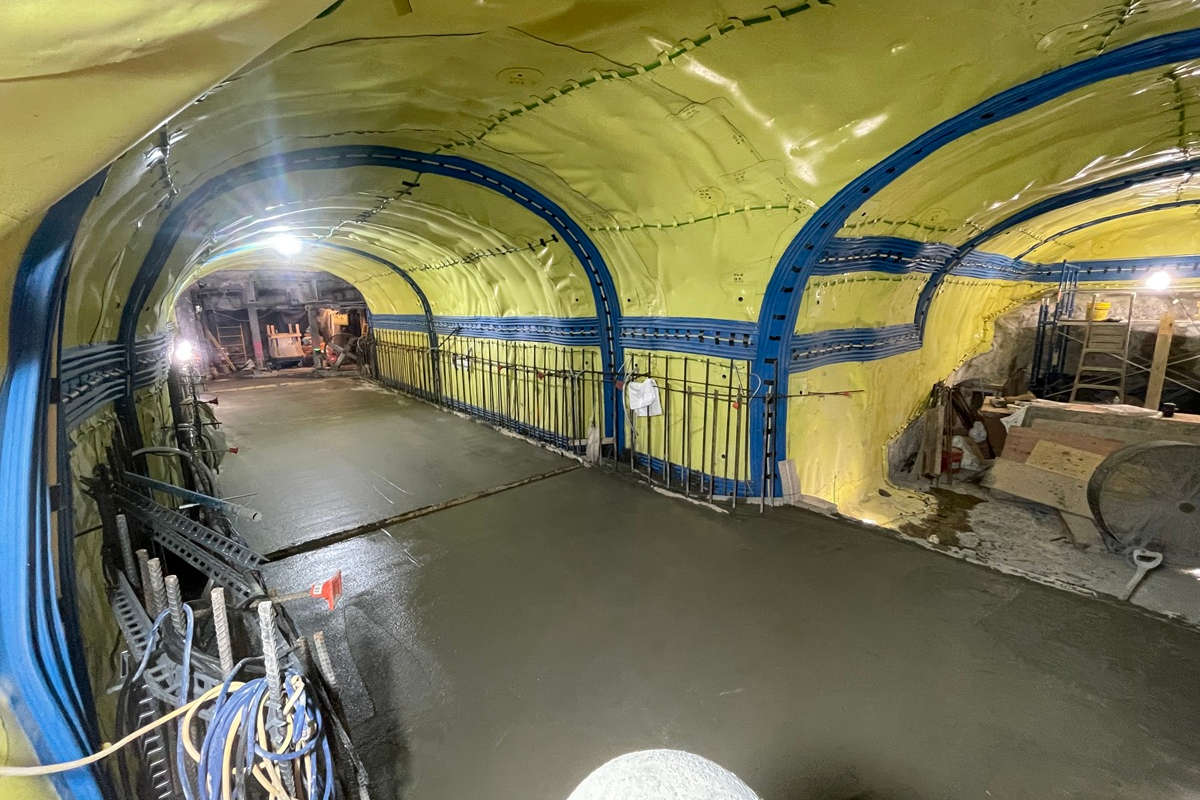
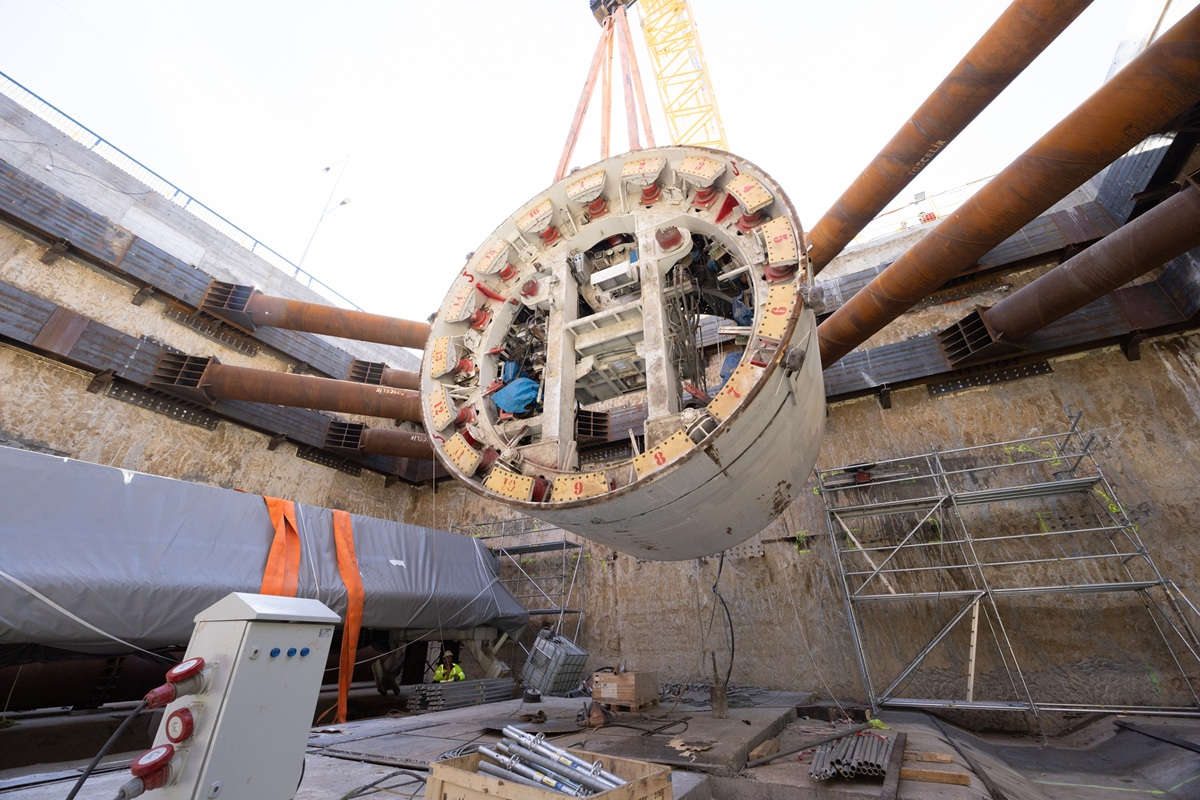
Access shaft for Bertha’s rescue required dewatering wells on the interior and exterior of the shaft to control groundwater flow and pressure.
Rescuing Bertha
Bertha, Seattle’s State Route 99 tunnel boring machine, broke through on April 4, 2017, completing its tunnel drive and marking the end of a 9,270-ft odyssey beneath Seattle. Her journey was not without its trials and tribulations. Bertha began mining on July 30, 2013. On Dec. 6, 2013, crews began to experience difficulties with TBM advancement. Bertha was stuck.
At the request of prime contractor Seattle Tunnel Partner (STP), Malcolm drilled a series of small-diameter exploratory probe holes in front of the TBM cutterhead and then drilled four 5-ft diameter shafts to enable STP to perform additional inspection and investigation.
After inspection and investigation was completed, STP restarted tunneling operations in January 2014, but found that Bertha’s internal main bearing had been damaged during the initial drive. Removal and repair of the main bearing and seals would require an access shaft large enough to dismantle the entire TBM cutterhead assembly, raise it to the surface for repair, and gain access into Bertha’s mechanical and structural elements.
For these emergency repairs, STP and Malcolm constructed a 120-ft deep by approximately 85-ft diameter semi-circular access shaft. The shaft consisted of secant piles and infill piles designed by STP/Brierley Associates as a non-reinforced compression ring.
The south Seattle waterfront sits on reclaimed land comprised of undocumented fill, debris and various organic deposits. These deposits overlie soft and loose marine sediments that lie on top of glacial till.
The complex glacial stratigraphy controls the nature of the groundwater flow. The permeability varies by orders of magnitude in adjacent stratigraphic units. Consequently, there are multiple perched groundwater-bearing layers along the tunnel alignment.
Piezometers installed near the south portal indicated pressure variations of up to 12 ft; some piezometers indicated artesian pressures of up to 4 ft above the ground surface. Tidal fluctuations also affected the groundwater levels.
Ten deep dewatering wells (designed by Bender Consulting) were installed in a horseshoe shape in front of Bertha to reduce hydrostatic pressure so that crews could safely perform their inspection.
After pricing several dewatering design options suggested by STP, a second dewatering system was installed in September 2014 consisting of five extraction wells inside the shaft, plus five wells on the outside to draw down the groundwater and thereby decrease hydrostatic pressures against the access shaft walls.
As excavation of the shaft interior progressed, new concerns arose about groundwater pressure in silty sand seams that might cause the shaft bottom to heave. Eight more wells were added to the outside of the shaft to reduce groundwater uplift pressure against the shaft’s bottom plug. Once the shaft was excavated, a wellpoint system and horizontal drains were also added to help relieve pressure.
The access shaft was completed in February 2015, allowing full access to Bertha. Repairs were completed in December 2015, and tunneling proceeded without further ado.
In this heavily congested urban area with complicated site infrastructure, variable soil conditions, and problematic and variable groundwater, the sequence of Bertha’s repair was considerably more involved than the highlights presented here. The overall wisdom gained from Bertha’s rescue was that it’s essential to tailor the construction techniques to the situation at hand, even as the situation changes.

Cutter soil mixing walls were an economical and faster construction technique for micro-tunneling access shafts on PG&E’s gas pipeline replacement project.
Tunneling Below a Major Interstate
Pacific Gas & Electric (PG&E) has more than 42,000 miles of gas pipeline throughout California. As part of its Gas Pipeline Replacement Program, PG&E opted to use a microtunneling technique to replace one of its 30-in. diameter lines in Fremont and Newark, California, where it crosses Interstate I-880 near the San Francisco Bay.
The microtunneling operation required a jacking shaft at one end (30 ft in diameter) and receiving shaft at the other (20 ft in diameter). Soil conditions at the site were predominantly interlayered sandy silty clay, sand and gravelly sand.
Access shafts are often built with reinforced secant pile walls. After studying the options, a design-build alternative was proposed, using a cutter soil mixing (CSM) compression ring for the shaft walls and jet grouting to seal the shaft bottom.
Malcolm was concerned about achieving a high-quality soil mix in the clay layer, but ongoing quality control measures indicated that the CSM panels were homogeneous, impermeable and achieved the required strength needed to ensure the walls would perform as planned.
The bottom of both shafts was 60 ft below ground surface, and approximately 35 ft below the groundwater level. Jet grouting proceeded in a circular pattern with overlapping columns. To verify the effectiveness of the jet grout plug, a geophone test program was conducted to measure the jet grout column diameter in real time during installation.
Excavation of the shafts proceeded without any external or internal dewatering. Water trapped within the shaft excavation was controlled and pumped out using a small pump.
G&E was extremely pleased with this access shaft system, with real-life proof that CSM walls can be a more economical and faster option for access shaft construction, and equally effective in controlling groundwater.

Cutter soil mixing walls at the Port of Miami Tunnel project provided dry conditions for TBM entry and exit.
Holding Back the Ocean
Sixteen thousand vehicles now bypass downtown Miami streets every day to access the Port of Miami directly from Interstates 395 and 95. Trucks and cars pass through two parallel tunnels completed in 2014 (one in each direction) that travel beneath Biscayne Bay, connecting the MacArthur Causeway on Watson Island with Port of Miami on Dodge Island.
The twin 42-ft diameter, 4,000-ft long Port of Miami Tunnel bores pass through highly permeable native silty sands and into multi-layered sands, cemented sands and highly porous limestone.
Miami sits next to Biscayne Bay. The groundwater table is within a few feet of the ground surface, so proper dewatering techniques were essential to the project.
In general, tunnel mining can proceed through groundwater and saturated soils. But groundwater must be controlled at the TBM entry and exit points. Under these conditions, groundwater control through pumping was simply not feasible.
Malcolm designed and constructed a watertight alternative to traditional dewatering using soil mixing. The temporary excavation support system at the tunnel ends served as access points for the TBM, and also helped to keep groundwater out of the construction area.
Parallel to the tunnel alignment, CSM walls were installed and reinforced with W-beam soldier piles and strand anchors. Across the access face, perpendicular to the alignment, a grid of unreinforced CSM panels was installed. Each CSM panel was about 9 ft by 4 ft, and up to 50 ft deep. A 12-ft diameter unreinforced lean mix concrete drilled shaft was then installed in the center of each grid element, resulting in a monolithic, watertight block.
That took care of the walls, but high groundwater still exerts uplift pressure on the excavation bottom. To counteract the uplift, a grid of drilled shafts was installed along the shallow end of the excavation and micropiles in the deeper portions. The drilled shafts and micropiles were tied into the concrete tremie slab to create a relatively solid, watertight working surface.
The lesson learned from the Port of Miami Tunnel is that creating relatively watertight entry and exit points is the only way to build tunnels at sites with a high groundwater table and permeable soil conditions. Using innovative construction techniques are often the only way to do that.
Tunneling Takeaway
Groundwater control techniques, both through extraction and exclusion, are an essential component of most tunneling projects.
Today’s larger and more powerful ground improvement equipment have enabled a huge advance in ground improvement techniques. Larger elements, such as CSM panels, large-diameter drilled shafts, and groundwater extraction wells, can be installed more economically. Advances in quality control techniques offer more confidence that ground improvement systems are built and will perform as intended, reducing the risk to tunneling operations.
Every tunneling project is unique. The major takeaway is that tunnel owners and prime contractors should rely on their ground improvement subcontractor’s expertise to bring both innovation and proven techniques to bear when wrestling with groundwater conditions. For tunneling, it’s all about control
Matt Kennedy is Malcolm Drilling Dewatering Division Manager and was project manager on the Seattle State Route 99 tunneling project (email: mkennedy@malcolmdrilling.com). Ihab Allam, PE, was Malcolm Drilling’s project manager on the PG&E pipeline replacement project. Nick Turus, PE, managed Malcolm Drilling’s work on the Port of Miami Tunnel project.
Comments are closed here.