Pressurized Face Tunneling: A Historical Perspective

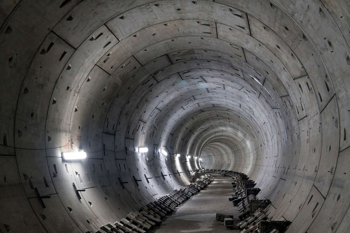
This 15.62-m (51.25-ft) diameter EPB TBM, one of the largest pressurized face machines in the world, was used to complete the Sparvo Tunnel in Italy.
[EDITOR’S NOTE: This is the fifth in a series of articles from Dr. Gary S. Brierley reflecting on the history of tunneling. This first article appeared in the August 2014 issue of TBM: Tunnel Business Magazine and examined tunneling from its ancient roots to the present day. Subsequent articles examine specific elements within the tunneling market, with particular attention paid to the U.S. market. This installment discusses pressurized face tunneling.]
The concept of using a shield to excavate tunnels in soil was introduced by Marc Brunel around 1830. It was also at that time that Lord Cochrane suggested the use of compressed air to stabilize soft or loose flowing ground at the face of excavation. In 1874, James Greathead designed a compressed air shield that was intended for construction of the Woolwich Tunnel in Great Britain. Greathead also proposed using grout to fill the void outside the final lining in order to prevent the compressed air from leaking into the tunnel. Although this machine was not used for the Woolwich Tunnel, its design set the stage for many similar machine designs over the next decade.
Coincident with experiments associated with compressed air, plans were also being made to “mechanize” the process of excavation and spoil removal. For instance, in 1876, John and George Brunton of Great Britain designed a “TBM” with a spherical rotating head equipped with spiral plates that cut the soil into rotating buckets, which then deposited the spoil onto a chute connected to a conveyor. The head of this machine was rotated using six hydraulic jacks and propelled by plates thrust against the sides of the tunnel.
In 1886 Frank Brown of New York designed a circular shield with a forward sloping face. Tunnel spoil was removed from the face by an auger projecting through the center of a full-face bulkhead, which allowed for the application of compressed air when required. For stiff ground, a removable manhole was provided through the bulkhead so that the excavation process could be facilitated by hand.
Between 1887-1889, Greathead designed another TBM with a central rotating cutterhead using wedge-shaped “spikes” to excavate the soil. A modification to this design included the possibility of utilizing water pressure both to stabilize the face and to facilitate spoil removal. Hence, this would seem to be a design concept for the first “slurry” TBM.
Other designers, such as J.J. Robins, J. Price and A.W. Farnsworth, developed machine designs utilizing conical heads, rotating arms, electric motors and gage cutters, which reduced friction and allowed the shield to turn horizontal and vertical curves underground – all of which took place prior to World War I. Interestingly, many of these and other designs were used by both sides during World War I in an attempt tunnel beneath enemy lines.
Fast forward to 1960. During the 80 years between 1880 and 1960, literally hundreds of tunnels around the world were constructed based on the concepts discussed above. Innumerable improvements were made to tunnel linings, mechanized shields, the application of compressed air, and tunnel seals in order to allow for longer and larger diameter tunnels to be built in a greater variety of ground conditions. During all of this time, however, the single greatest problematic ground condition was granular soil below the water table resulting in a flowing ground condition.
Unfortunately, this was also the most difficult ground condition to control with compressed air. Unbalanced water and soil pressure at the face of tunneling is difficult to control with a constant air pressure, which allows either a loss of soil at the crown and surface settlement or, worst of all, a blowout – a loss of soil at the invert resulting in “quicksand” and the diving of the shield.
In addition, in contaminated ground, adjacent structures can be inundated with hydrogen sulfide or gasoline vapors as a result of air escaping from the tunnel. Hence, because of these and other problems, tunnel designers became obsessed with the desire to control the face with a fluid pressure rather than air pressure.
The first “slurry” shield used in the United States was designed by the Gardner Engineering Corp. in 1960 for a 10-ft diameter drainage tunnel in Houston, Texas. The soil was excavated with a rotating cutting chain and mixed with water. After mixing, the soil was removed from the face as a slurry. Interestingly, no pressure was applied to the face with this slurry in order to assist with face stabilization.
In 1964, Mott, Hay and Anderson was awarded a British patent for the “Bentonite Tunneling Process” that resulted in the production of an experimental shield by Robert L. Priestly in 1971. During this same time frame, Markham & Co. Ltd, also of Great Britain, produced three pressurized shields for tunnel construction in Mexico City. Those shields, referred to as Universal Soft Ground Tunneling Machines, were designed to resist the entire soil and water pressure of Mexico City’s notoriously unstable ground. Markham was retained to supply the machines, which were operated by contractors in Mexico City with varying degrees of success. The machines themselves, however, demonstrated all of the basic features of pressurized face slurry TBMs.
Early experiments with slurry shields in Japan began in the late 1960s and led to the design and construction of a 24-ft diameter slurry shield by Mitsubishi Heavy Industries in 1970 for work on a railway project. After reviewing every possible existing method for building those tunnels, the Japanese decided that the only conceivable method would be a fluid pressurized face machine. Following successful completion of this tunnel, the Japanese proceeded to design and manufacture numerous additional slurry TBMs.

The “shield” was patented by Marc Isambard Brunel in 1828. His shield was only used for the construction of one tunnel in the 1820s, the first Thames River Tunnel, but that effort was so time consuming and so expensive that no shield tunneling was attempted again until the late 1860s.
Also active in this time frame was the Wayss & Freytag Corporation in Germany. In 1974 Wayss & Freytag developed the first so-called Hydroshield for construction of a 15-ft diameter sewer tunnel under Hamburg Harbor. Fluid face pressure in the excavation chamber was maintained with air pressure behind a rear bulkhead. One other interesting feature of this TBM was a forward cutting wheel that could be moved forward or backward in order to deal with variable ground conditions. Lacking an adequate sealing mechanism for the TBM, it was necessary to use air pressure in the tunnel for most of these two tunnels.
The first discussion of slurry shield tunneling in the RETC proceedings appeared in 1976 in Chapter 16, Slurry Shield Method in Japan. In the 1979 edition of the RETC proceedings, Wayss & Freytag discussed their experiences with the Hydroshield in Chapter 27, Contractors’ Experience with the Hydroshield Tunneling System. Both of these papers provide a good deal of additional information about the history of slurry shield technology.
All early Earth Pressure Balance (EPB) tunnels were constructed in Japan beginning in 1974. In general, this method of tunneling required a soil mass with at least 20% fines in order to “plasticize” the soil in front of the bulkhead. With time, this requirement was greatly modified as a result of the use of various “conditioners.” The key to success for an EPB machine is to carefully balance the amount of soil removed from the ground with the computed volume of excavation of the shield. In this way, disturbance to overlying or adjacent existing structures can be avoided. The EPB method also has the distinct advantage of providing a vertical pressure gradient across the face of excavation which helps to stabilize both the crown and the invert.
Interestingly, and as discussed above, the concept for some form of slurry or plastic soil mass at the face of excavation was understood from the late 1800s, but the structural, mechanical, electrical and hydraulic necessities for such a machine were simply not available until the 1960s.
The first discussion of EPB tunneling in the RETC proceedings appeared in 1979 in Chapter 30, Earth Pressure Balanced Shield Method. In the 1981 RETC proceedings, a paper titled Shield Tunneling Performance and Behavior of Soft Ground, Osaka, Japan, discusses other early case histories utilizing this method.
To say that slurry face and EPB machines revolutionized soft ground tunneling would not be an exaggeration. Larger tunnels in dramatically unstable ground conditions became not only possible, but could be constructed at a cost that was reduced as compared to mechanized shield tunneling with compressed air. The development of design and construction procedures for soft ground tunneling projects beginning in the early 1970s to the present day has been trully astounding.
To date, this series of articles has discussed ancient history, drill and blast, rock TBMs early shields, and small diameter tunnels. In general, there were two outstanding periods of tunneling innovations, one in the late 1800s and the other in the late 1900s with the most outstanding period of tunnel development being from 1970 to about 1990. During that time frame, the ability to design and construct tunnels in both soil and rock saw enormous improvements to a degree that the cost of tunneling was actually reduced in real dollars.
It is also interesting to note that this time period included the bulk of experiences for old timers in the industry such as myself. It was a tremendous opportunity and a very exciting time to be part of this latest and greatest period of tunnel innovation.
References:
Copperthwaite, C.; Tunnel Shield and the Use of Compressed Air in Subaqueous Works, 1906, D. Van Nostrand Co., New York.
Stack, B.; Handbook of Mining and Tunneling Machinery, 1982, John Willy & Sons, New York.
Maidl, B. et. al; Mechanized Shield Tunneling, 1996, Ernst & Sohn, Berlin.
Gary S. Brierley is president of Dr. Mole Inc. He began his career in 1968 with the Bachelor’s Degree in Civil Engineering from Tufts University and the Masters and Doctoral Degrees from the University of Illinois in 1970 and 1975, respectively. During that time Dr. Brierley was fortunate to work on the instrumentation program for DuPont Circle Subway Station in Washington, D.C., a project that formed the basis for his doctoral dissertation. Since that time, Dr. Brierley has devoted his entire professional career to the design and construction management of underground openings.

Comments are closed here.