Shaft Lining with Dry-mix Shotcrete

Close up of application of finish coat dry-mix shotcrete from floating deck.
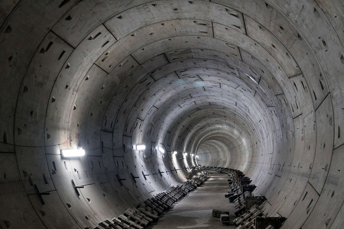
The Greater Vancouver Water District (GVWD) in British Columbia has constructed a new water supply main in a tunnel under the Fraser River, just downstream of the Port Mann Bridge. This new water main will help ensure the continued, reliable delivery of clean, safe drinking water to municipalities south of the Fraser River.
The steel water main was constructed within a 1,000 m long x 2.8 m inside diameter tunnel driven through soil, underneath the riverbed, connected by a 50 m deep shaft at the south end of the tunnel and a 60 m deep shaft at the north end of the tunnel. The shaft on the north side of the Fraser River was constructed with interlocking slurry wall panels to create a circular shaft approximately 8.16 m in diameter and 60 m deep.
Final design required a 1.5-m thick circular reinforced cast-in-place (CIP) concrete wall to be poured within the slurry wall. The design of the shaft required a bond breaker/slipliner between the slurry wall and CIP wall, such that in the event of an earthquake, the circular reinforced cast-in-place concrete wall can move freely relative to the slurry wall. An 8.0-m diameter shotcrete wall was to be applied to the slurry wall and a bond breaker installed against the finished shotcrete wall. Dry-mix shotcrete was selected to be applied to the slurry wall. Screed rails, which were to be installed every 1.5 m, had a specified verticality tolerance of 10 mm between rails. The specified vertical tolerance of the final shotcrete wall was +5/-3 mm between screed rails.
Background
The Port Mann Main Water Supply Tunnel consists of a 1-km long tunnel underneath the Fraser River from Surrey to Coquitlam, B.C. The tunnel contributes to the water supply from the Coquitlam Reservoir and is part of the expansion and seismic upgrade of the GVWD water transmission system. The tunnel boring machine (TBM) created a 3.5-m cut that enabled the installation of segmental lining that measured 3.3 m outside diameter and 2.8 m inside diameter.
Shafts were sunk at both the south and north ends of the tunnel. At the north shaft, the seismic design required the installation of a slipliner between the outer slurry wall and the final reinforced cast-in-place liner in order to eliminate the possibility of composite action between them in the event of seismic induced deformations.
Shotcrete Lining Construction Method
A two-part system was developed that included shotcreting a smooth, circular wall against the slurry wall and then fastening a plastic liner to the wall. A cast-in-place wall was then poured against the plastic liner which would act as a bond breaker during a seismic event.

Completed shotcrete wall with plastic slip liner installed.
The contractor, McNally/Aecon JV, working together with the engineer of record, Fraser River Tunnel Group (consisting of Ausenco, McMillen Jacobs Associates and Golder Associates), developed the following shotcrete construction method. A total of 12 steel columns were evenly spaced around the shaft collar. A steel hollow structure section (HSS) was welded to the top of each column. An FG-LL31 self-leveling Zenith Laser Plummet was screwed into the HSS with bolts, so that the laser line shot straight down with an accuracy of +/-5mm/100m. The laser line was offset 50 mm from the theoretical perimeter of the 8-m diameter finished wall.
Screed rails were made from 13 mm round bar that was bent to match the radius to the shaft final diameter. The screed rails were fixed in place by drilling and grouting several steel dowels circumferentially around the shaft wall every 1.5 m. For each screed rail, three lasers were used to position a curved aluminum template which was clamped to the drilled dowels. The screed rails rested on the dowels and were clamped to the aluminum template. Once in the correct position, the screed rails were welded to the dowels and the template was moved to the next screed rail position. Rails were installed to a tolerance of +/-10 mm, becoming the guide for shotcrete application.
RELATED: New Metro Vancouver Outfall Tunnel to Support Expanded Treatment Capacity
Performing this work in a 60-m deep shaft required a mobile platform. The platform was utilized in two ways during construction. First, a crane lifted platform was used to install screed rails. Once complete, the platform was transformed into a floating deck by attaching hollow plastic floats to the bottom. Shotcete was applied from this floating deck. The floating deck had many advantages during shotcrete application. It was able to support all manpower, equipment and rebound and cuttings. Harnesses and lifelines were not required and there were no support cables to get in the way during shooting.

The shaft was constructed with interlocking slurry wall panels to create a circular shaft approximately 8.16 m in diameter and 60 m deep.
Once screed rails were installed throughout the shaft, the shaft was filled with water and the platform was converted to a floating deck. Starting at the bottom of the shaft, the shotcrete liner procedure was as follows:
- Apply base course shotcrete to a height of 1.5 m, screed rail to screed rail. Approximately 25 mm was left for the finishing course.
- Shaft filled with water until floating platform raised to next lift.
- Shoot next lift, raise platform and repeat the process.
- Finish base course to the top of the shaft – approximately 36 lifts.
- Apply finishing course to each lift from the top down.
- Apply finishing course, dewater shaft until platform is lowered to next lift, apply finish course and repeat the process.

Crane lifted platform during rail installation.
Shotcrete Mix Design
The water table surrounding the north shaft was controlled by tide and river levels and was often near ground surface elevation. As such, the slurry wall was under constant water pressure and leaks were present throughout the shaft. A dry-mix shotcrete with suitable accelerator dosages was selected to help mitigate water ingress.
The specified compressive strength was 40 MPa at 28 days. The main purpose of the shotcrete was to act as a filler to bring the slurry wall to a circular shape. The following mix designs were used on the project.
Mixture B1 was applied for the base course shotcrete liner. Whenever water was observed coming out of the slurry wall, mixture B2 was used to obtain faster set. Initially for dry areas, mix B3 was used to apply the finishing coat. During construction in October and November, the finish course shotcrete set more slowly because of cooler ambient temperatures and mixes B4, B5 and B6 were used as needed to reduce the setting time and speed up the finishing process. The accelerator dosage was designed such that the finishers had enough time to screed and trowel the final shotcrete surface to the tolerance requirements. Heaters and hot water pressure washing were also used to increase the ambient and substrate temperature of the base course in the shaft.
Pre-construction trial shooting was performed to ensure the quality of the shotcrete mixture, in addition to qualify nozzlemen. Trial shooting involved the use of test panels that mimicked the curvature and thickness of the panels.
Quality control tests mainly consisted of compressive strength tests, which were conducted on cores extracted from test panels.

Table 1: Pre-bagged dry-mixed shotcrete mixture proportions for 1.0m³
Dry-mix Shotcrete Set Up
The dry-mix shotcrete process facilitated easy access, allowed frequent movement of equipment, and was provided with dust control. The dry-mix shotcrete process results in higher rebound compared to the wet-mix shotcrete process. When using dry pre-bagged materials, dry-mix shotcrete application requires the use of a pre-dampener with a hopper that can load 1 cu.yd of pre-bagged materials into a rotary gun. A conveyer hose, air compressor providing an air flow at 850 cfm (cu.ft/min) at a pressure of 0.83 MPa, and nozzle connected to a water supply hose were used. The use of a pre-dampener is essential for the dry-mix shotcrete process. It pre-wets the dry-mix materials to a moisture condition of about 4-6%, reducing dust, facilitating conveyance of the material in the hose, and reducing the risk of shock from static electricity.

Shotcete was applied from this floating deck, which had many advantages during application.
The dry-mix machine and pre-dampener were set up at the surface, and hoses 35-60 m long were used to convey the materials to the nozzleman on the floating deck.
The base course shotcrete was up to 180 mm thick and was made with ACI 506 Gradation No. 2 shotcrete, with 3% accelerator. It was used to fill the gap between the slurry wall and steel screed rails and to create a smooth circular surface. Approximately 25 mm was left for final finish shotcrete application.
The following procedure was followed for finishing:
- Blow off excessive water on the surface of the first layer of shotcrete
- Apply shotcrete
- Finish shotcrete
Construction sequence and timing are critical. The surface moisture condition was kept saturated surface dry (SSD) during Step 1. The finishing was conducted right after Step 2. It was critical to finish the final shotcrete surface before the dry-mix shotcrete (with accelerator) reached initial set. This was usually about 5 to 10 minutes after shotcrete application.
RELATED: Tunneling Complete in Fraser River for Port Mann Water Supply Main
Construction Challenges
Cold weather shotcrete
As the project progressed into November and December, the ambient temperature at the project site dropped to 5 C or lower. This delayed setting of the shotcrete and affected finishing practices for the shotcrete finish course. Several heaters were installed in the shaft, and the base course surface was cleaned with high pressure hot water and steam, with temperatures of 90-100 C. The shotcrete temperature was kept at 12 C or higher which provided an environment suitable for cement hydration with proper setting and early age strength development. Additionally, the shaft was covered and heated overnight and dry mix bags were kept above 20 C using tarpaulins and heaters.
Finishing
The base course shotcrete was left with a nozzle finish. The finish course was finished to a smooth surface by steel trowels. A total of a three mix designs were applied to the walls. In areas with little to no water present, mix B3 with no accelerator was applied. In areas with light to moderate flows of water, mix B4 with 1.5% accelerator was applied. In areas with heavy water flows, mix B6 with 3% accelerator was used. In these last areas, it was often required to install weeping pipes to allow a path for water to escape during application and setting. Mix B6 took approximately 5-10 minutes to set in the cooler weather, which allowed the finishers ample time to finish, while setting fast enough to stop water inflows. Weeping pipes were later removed and holes were dry packed with grout.
Water Leakage from the slurry wall
This shaft is alongside the banks of the Fraser River and is subject to high groundwater levels. Water ingress is quite common in a slurry wall shaft within the cold joints between overlapping panels. The high hydrostatic pressure from the leaks made it nearly impossible to stop water inflows. Sodium silicate grout was injected behind the shaft slurry wall which helped to reduce water leakage through the slurry wall. Additionally, the base course substrate was dried using an air lance (blow pipe) and the shotcrete nozzle with compressed air to bring the surface to a saturated surface dry (SSD) condition immediately prior to shooting the finish course. This was found to be effective for base course shotcrete application and final finishing most of the time. However, there were some occasions where a build-up of water pressure on the base course shotcrete behind the finish course caused bulges in the finish course shotcrete. These areas were cut out and repaired with highly accelerated shotcrete and a weeping pipe.
Summary of Dry-Mix Shotcrete Work
- Hanging/Floating Deck: The hanging/floating deck was an innovative way to travel between lifts during screed rail installation and shotcrete application. It was cost effective and reduced the construction schedule and enabled efficient water curing for the shotcrete lining compared to other decking options, such as scaffolding the entire shaft.
- Dry-Mix Shotcrete Application: Dry-mix shotcrete was selected due to its flexibility of operation, fast setting time, and suitability to deal with water leakage into the shaft. The pre-dampened dry-mix shotcrete was applied with good control over rebound and overspray. It should be noted that rebound or waste was far less than expected, approximately 10-20% of the total volume. Dry-mix shotcrete pre-bagged material worked well in providing a final liner construction with varying thickness. Rigorous QC inspection and testing confirmed that a good quality shotcrete lining was applied.
- Cold Weather Shotcrete: During cold weather, when ambient temperatures fell below 5 C, additional precautions and protection measures were implemented. Hot water pressure washing was able to properly prepare the base course shotcrete and increase the surface temperature to be appropriate for receiving the final finish course shotcrete with the selection of appropriate accelerator dosages. Keeping the area warm with heaters as well as keeping dry mixed bags warm prior to use was also effective. The finish course shotcrete was designed to set up quickly, while still allowing sufficient time for steel trowel finishing to the specified tolerances.
Conclusions
The Port Mann Project started in January 2011, and finished in February 2017. The shotcreting of the North Shaft started in August 2013 with screed rail installation followed by shotcreting in September 2013. Final patching of the shotcrete wall finished in January 2014. Upon completion, the following conclusions were reached:
- Dry-mix shotcrete, when properly applied, can provide a good quality shotcrete lining, in particular, for liners with irregular shapes and varying thickness.
- The floating deck construction method used is an innovative construction method for shaft lining construction. It improved the quality of shotcrete construction, reduced rebound and overspray, reduced the construction schedule, labor and materials costs, and reduced the overall cost of the project.
- Special measures need to be adopted to deal with the build-up of water pressure behind a layer of freshly applied shotcrete. The procedures described in this report were effective in dealing with this problem.
Lihe (John) Zhang, Ph.D., P.Eng, Shotcrete Consultant, LZhang Consulting & Testing Ltd; D.R (Rusty) Morgan, Ph.D., P.Eng, Shotcrete Consultant; Ted Walter, President, Can Tech Shotcrete Inc; Brian McInnes, P. Eng., Project Engineer, McNally Construction Inc.; Allen Mitchell, P. Eng., Senior Project Engineer, Metro Vancouver, Water Services Department; Andrew Rule, P. Eng., Project Manager, Aecon Infrastructure Inc.

Comments are closed here.