Advancements in Large Diameter TBM Tunneling
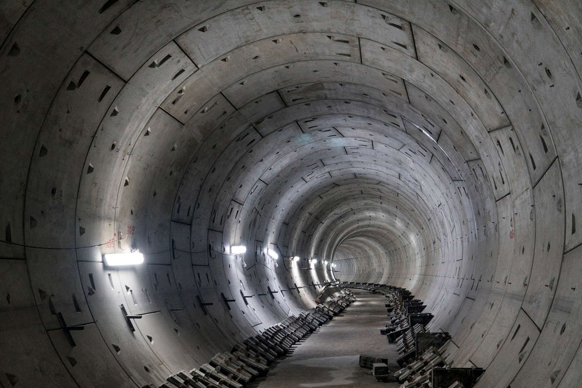
Over the past two decades soft ground and mixed face TBM tunnels have increased in diameter such that the term ‘large diameter TBM tunnel’ has become common usage. However, there is no actual definition of what constitutes ‘large.’ Therefore, in this article ‘large’ will refer to any tunnel of 30 ft, or greater, internal diameter.
Prior to the development of closed face TBM technologies large diameter soft ground tunnels were confined to favorable tunneling strata and constructed using compressed air. Examples include the Blackwall Tunnels (1897) under the Thames in the impermeable London Clay in London or the Hudson Tunnel (1927) and the Lincoln Tunnel (1938) in the United States. Many deaths occurred during the construction of these tunnels under difficult ground conditions. In 1997 the Tokyo Bay Aqualine Tunnel opened to traffic. This tunnel was 23 years in planning and 9 years in construction. It comprises twin two-lane 39-ft ID highway tunnels 9.6 km long. The tunnels were bored through soft alluvial soils by eight Kawasaki slurry 46-ft OD TBMs. The 23-year gestation of the project is in part due to the absence of a tunneling system capable of handling the ground conditions both safely and economically. This project represents one of the first major projects reliant on pressurized closed face TBM technology. Since this achievement, the appetite for large diameter tunneling in challenging ground conditions has grown.
Closed face pressurized TBMs that were developed specifically to operate in either loose non-cohesive soils below the groundwater table and soft clays are now commonly used to excavate through mixed face conditions of soil and rock, and full faces of rock.
The two principal types of closed face pressurized TBM, the slurry and earth pressure balance (EPB) have been joined by hybrid TBMs that can operate in either mode depending on ground conditions. However, the TBM diameter must be large enough to accommodate the two separate mucking systems, conveyor belts and the slurry circuit plus segment and other materials transport and ventilation ducting.

TM-CLKL: 58ft Dia Slurry TBM

Liang Tang Tunnel: 58ft Dia EPB TBM
Lining Design
While for the most part the design methods and procedures for designing large diameter tunnels are the same for any other segmentally lined tunnels there are specific areas that require special attention. In particular the longitudinal behavior.
In soft and loose soils, shafts can comprise fixed points anchoring the floating tunnel structure. This fixity leads to the tunnel adopting a sagging and hogging profile. This action occurs irrespective of tunnel diameter but the larger the diameter the greater the consequences. These can include local overstress at the crown and invert in the circle joint as the rings attempt to conform to the profile by pivoting about either the crown or the invert. This overstress should not lead to a catastrophic failure but it can comprise sealing gaskets causing long-term maintenance issues. Either by creating seepage paths behind the gasket or reducing the compression force closing the gasket. In smaller diameter tunnels this can be mitigated by using a flexible joint between the segmental lining and the shaft wall. However, in large diameter tunnels this may not be sufficient and additional measures may be required to limit the longitudinal movement. This could be tensioned through bolts in the circle joint, to increase the longitudinal stiffness and limit deflection.
Monitoring and Control of TBM Operating Parameters
The physical principles by which these TBMs operate are well understood. However, less well known is the essential role that the ancillary systems play. These include the PLC and SCADA systems that monitor, log and facilitate the control of the TBMs in the ground. The sheer volume of data that a TBM system generates is staggering and potentially bewildering. These systems can be divided in two principal functions. Those that monitor the ‘health’ of the TBM and those that monitor the performance of the TBM in the ground.
An example of the former is the continuous measurement of temperature of the various lubricants and other fluids in the main bearing and other moving parts. The latter include face pressure, flow volumes and density of the slurry in the slurry circuit to determine the volume of muck excavated with each TBM advance. Similarly, belt scales and laser systems determine the volume of muck excavated in an EPB TBM. The larger the TBM the more critical these measurements are in order to assess the ground behavior and minimize ground loss and potential settlement. It is becoming increasingly common to link the real time readings of ground movement instrumentation to the TBM PLC. This allows the measured ‘bow wave’ settlement to be used as a predictive tool to determine total settlement allowing the TBM operating parameters to be adjusted as the TBM advances.
Parallel Operations
Large diameter tunnels allow parallel operations to be undertaken during construction unlike for smaller tunnels where these activities have to be undertaken in series after completion of each operation. On AECOM’s Chong Ming South Tunnel a precast central deck element was placed immediately behind the TBM that provided materials access and formed part of the permanent road deck. The precast element was followed in turn by cast in place concrete works to complete the road deck. AECOM’s Tuen Mun Chek Lap Kok Link (TM-CLKL) tunnel represented a significant progression with full width precast deck elements being placed behind the TBM and the overhead vent similarly formed of precast elements reducing cast in place work to a minimum.

TM-CLKL: Precast Deck Unit

Chong Ming South: Central Precast Deck Unit
Another innovation made possible by large diameter TBM construction is mechanized cross passage construction. This was carried out on TM-CLKL tunnel using a slurry microtunneling TBM with a pipe jacked lining.

TM-CLKL: Cross Passage Construction

Tool replacement or cutterhead maintenance remains the most high-risk activity in the tunneling operation. It is possible to minimize the potential for unscheduled interventions by creating grouted blocks as safe havens in which cutterhead inspection and maintenance can be carried out in atmospheric conditions. In addition, various technologies exist to change cutting tools and clear blockages without the need for entry to the pressurized cutterhead.
On the two Herrenknecht slurry TBMs employed on the Chong Ming South tunnels access to a limited number of tools was provided via cutterhead spokes. These tools could be removed and replaced through a stuffing box system. Recent advancements in large diameter TBMs provide for disk cutters and cutting knives to be replaced atmospherically from the back of the cutterhead using guillotine type doors. Examples include the Istanbul Strait Crossing TBM and Bertha for the Alaskan Way Tunnel TBM.

Chong Ming South TBM: Person-Entry Through Cutter Head Spokes for Cutting Tool Changes

Chong Ming South: TBM in Recovery Shaft

TM-CLKL: TBMs in Recovery Shaft

While the technologies outlined above have been proven successful on large diameter TBMs of both the slurry and EPB type, the need for entry in to a hyperbaric atmosphere remains if only to recover and repair these tools in the event of a mechanical breakdown, or damage.
Another trend is tunneling at deeper depths. For example, the Chong Ming South Tunnel is located 200 ft below the Yangtze surface and similarly the Westerschelde Tunnel is at a similar depth below the Scheldt Estuary in the Netherlands. Hyperbaric interventions would have to be carried out at pressures of up to 8 bar on these projects. For the Westerschelde tunnel, modifications were required to the cutterhead approaching the deepest section of the tunnel. A compressed air intervention could not be carried out at 8 bar without exposing personnel to unacceptable safety hazards. Therefore, the saturation diving technique was employed. This comprises a team of divers living in a hyperbaric habitat and being transported to the TBM in a pressurized shuttle that docks with an airlock on the pressure bulkhead.

FAT /TBM Hyperbaric Shuttle Connecting Flange

TM-CLKL: Hyperbaric Shuttle
The divers breathe mixed gases throughout their stay in the habit on occasion working for months at a time before decompression. Decompression can take a number of days as the pressure is reduced in a series of calibrated steps until atmospheric pressure is achieved. Experience gained on the Westerschelde Tunnel informed the design and TBM technical specifications for the TM-CLKL where the technique was employed to supplement the robotic technologies also available to inspect and replace cutting tools. Similarly, for the Istanbul Strait Crossing subjected to 12 bars of water pressure, four hyperbaric interventions were required.
Closing Remarks
TBM diameters have increased over the past decades to the point where planners and some others believe there is no limit to the diameter that can be built. While this may be true in the future the increase in TBM diameter is at, or approaching, the practical limit based upon current technologies. Therefore, careful consideration and caution must be applied in planning for even larger TBM tunnels.
About the Author
Bob Frew, is AECOM’s Subject Matter Expert of large diameter TBM tunnels. In this role, he brings to the clients in the United States his global expertise and lessons learned of large diameter tunnels throughout the world. As a tunnel specialist with more than 40 years of experience in tunnel design and construction, Frew’s diverse expertise encompasses design, project management and construction management for all types of tunnel and underground structures including roadways, rail, metro, water, and sewer tunnels. He has worked on such notable projects as the Channel Tunnel Rail Link in England, the Copenhagen Metro, the Westerschelde Tunnel in The Netherland, and the Chong Ming Tunnel in Shanghai. His TM-CLKL project in Hong Kong holds the world record for the largest TBM at 57.75 ft in diameter and is the recipient of numerous awards including the ITA’s 2019 project of the year award.
RELATED: New Era Beginning in Seattle
Comments are closed here.