Building Lake Mead’s Third Straw
Continuous 12-day Pour Challenges Barge-mounted Putzmeister Concrete Placing System
A continuous 12-day concrete pour tested the stamina and performance of a barge-mounted Putzmeister concrete placing system to place 12,000 cu yd of concrete 390 ft below the water’s surface — an extremely long-distance feat for pumping concrete underwater. The pour secured the opening of a raw water intake structure for the Third Straw project on Lake Mead — one of the largest U.S. municipal water projects.

Step 1: Ready mix trucks are loaded on a transport barge, eight at a time, to deliver concrete for a tremie pour almost three miles (5km) from shore.
Currently, the city of Las Vegas draws about 90 percent of its drinking water through two horizontal intake pipelines, or straws, in the Lake Mead reservoir, tapping the Colorado River behind Hoover Dam. However, the depth of the drought-stricken lake has fallen more than 100 ft in the past decade, and to avoid a potential crisis, the third straw is being built deeper in the lake. Its objective: To protect the community from a water shortage in case the lake drops to a level that shuts down the existing two straws.
With an estimated cost of over $800 million, the officially named Intake No. 3 project is the most complicated and expensive construction job undertaken by Southern Nevada Water Authority (SNWA). In 2008, SNWA awarded the design-build contract to Vegas Tunnel Constructors LLC, a joint venture of S.A. Healy Co., Lombard, Ill., and Impreglio S.p.A., Sesto San Giovanni, Italy.
Joining Forces
The project requires multiple construction facets, with a major concrete placement task that took center stage in March 2012. A Putzmeister concrete placing system supplied by Ralph’s Concrete Pumping (Ralph’s) of Seattle handled the complex process, utilizing two Series I detachable placing booms — a 36-m and 38-m, two placing boom towers, two trailer-mounted concrete pumps — a BSA 14000 HP-D and a BSA 2109 H-D, and Putzmeister’s concrete delivery line with ZX ends. This particular delivery line system was used to alleviate the concern about concrete spillage in the water, as the line and couplings are leak-proof and rated for extremely high pressures.

Step 2: Concrete is discharged from ready mix trucks onto Maxon conveyors located on the equipment barge
“The job was a far more logistically challenging and complex one than I ever imagined it would be when I first was contacted by Maxon Industries to coordinate Putzmeister equipment for the project,” says Skip Gribble, owner of Ralph’s.
Putzmeister and its Special Applications Business (SAB), a team of experienced engineers, focuses on the synergies of Putzmeister’s family of products, which includes concrete pumping equipment, Telebelt telescopic belt conveyors, Putzmeister Shotcrete Technology and Putzmeister Pipe Technology, in addition to a partnership with Maxon Industries Inc. This partnership provides a complete systems approach that offers a wide range of complementary products to projects around the world in the tunnel, mining, dams, power generation, transportation, marine and offshore industries.
A Complex Process
A raw water intake structure, basically a concrete-and-steel funnel 100 ft tall and weighing 1,200 tons, was floated almost 3 miles from shore and methodically sunk to the bottom of the lake, making its home in a huge 60-ft deep pit that was previously blasted with explosives. A single, continuous 12,000 cu yd concrete pour was needed to fill in the hole and keep the structure in place.
The multifaceted concrete placing process started on shore with an on-site batch plant set up to continuously supply a specially designed concrete mix. Ready mix trucks, each loaded with 10 cu yd of concrete drove onto a transport barge, eight at a time, to be ferried across the water with their drums turning. Their destination — an equipment barge about 3 miles from shore. To maintain a non-stop flow for more than 250 hours, three transport barges kept 32 ready mix trucks cycled between the shore and barge.

Step 3: The concrete is conveyed into a Maxcrete remix surge hopper, which provided a high capacity to ensure a continuous concrete flow to the BSA 14000 HP-D trailer-mounted pump when transitioning to the next barge of ready mix trucks.
At the equipment barge, the crew set up the placing system that was specifically chosen to place concrete in the most efficient manner and ensure the mix maintained its specified properties. Due to the critical nature of the pour, two complete concrete equipment setups were installed on the barge — one system would be operational while the second was on standby for maintenance and backup.
Once the ready mix trucks reached the equipment barge, concrete was discharged onto a 40-ft Maxon conveyor that transferred the concrete to a second Maxon conveyor needed to elevate the concrete into a Maxon Maxcrete remix surge hopper. The Maxcrete, with bi-rotational agitator shaft, allowed retempering the concrete as needed from the 1,200-plus loads of concrete, helping to ensure quality concrete from the first to the last yard. The 10-cu yd Maxcrete also provided surge capacity during the transition when the first transport barge would pull away and the next would arrive. This would provide a continuous concrete flow to the BSA 14000 trailer-mounted pump, paired with the 38-m placing boom as the primary operational system.

Step 4: A 38-meter Putzmeister placing boom places the concrete into a tremie pipe that sends the concrete 390 ft underwater.
In turn, the high-pressure trailer pump pumped the mix through 20 ft of Putzmeister delivery line to the placing boom mounted on a 20-ft tall freestanding tower. As with all Putzmeister placing booms, no counterweight is required; therefore, it offered a lighter weight on the equipment barge floating atop the water. The placing boom, capable of extending 108 ft, 7 in. horizontally, maneuvered its four-section boom into a 10-ft diameter tremie pipe that delivered the concrete 390 ft to the lake’s bottom.
No divers were in the water guiding the work. Instead, the crew at the surface used sonar, GPS sensors and a single remote-controlled submarine to monitor what was happening below the water’s surface.
Equipment Requests
“The placing boom was powered by a 3-cylinder diesel power pack instead of the more commonly used electric power pack, which would have required a great deal of power from a generator,” says Gribble.
“Plus, as a precaution, the job specified that our equipment use a biodegradable vegetable oil, instead of hydraulic oil, during operation on the barge,” notes Gribble. “The equipment performed to expectations with the special oil.”
“At times, concrete output peaked over 100 cu yd an hour, which is a high volume for this type of application, especially with the distance and steps involved to consistently move the concrete from the shore to the bottom of the lake,” adds Gribble.
Wind Causes Havoc
The pour was proceeding as planned until the sixth day when strong winds gusted up to 60 mph on the lake, sending waves crashing over the platform and causing treacherous conditions for the barges ferrying ready mix trucks. The job shut down for nine hours.
Although strong winds caused a temporary delay, it didn’t affect the quality of the finished product because the concrete mix had a 30-hour set time. The set time was initially specified to provide ample time to inch the concrete around the intake structure and add new layers before hardening; however, the 30-hour set time also accommodated the unexpected wrath of nature.
Three-Mile Journey
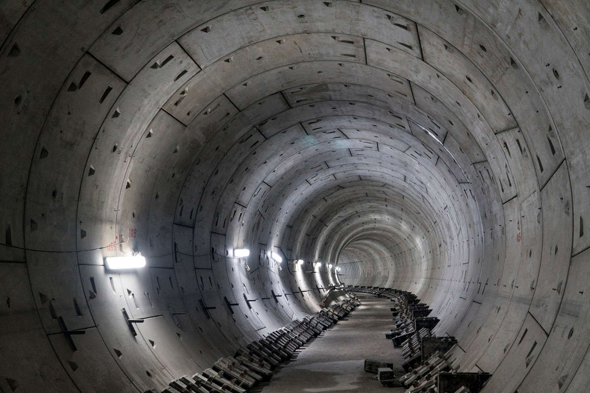
Eventually, the intake structure will connect to a 20-ft diameter, 15,000-ft long concrete panel reinforced tunnel under the lake bed. This will occur when a tunnel-boring machine on a 1,571-day mission reaches the intake structure, after digging 3 miles through solid rock beneath Lake Mead. The entire raw water intake project is presently slated for completion in early 2014.
INTAKE NO. 3 FACT SHEET
Owner: Southern Nevada Water Authority—Las Vegas, Nev.
General Contractor: Vegas Tunnel Constructors LLC—a joint venture of S.A. Healy Co., Lombard, Ill. and Impreglio S.p.A., Sesto San Giovanni, Italy.
Ready Mix Supplier: Precision Aggregate Products LLC—Mesquite, Nev.
Concrete Placing Contractor: Ralph’s Concrete Pumping, Inc.—Seattle
Equipment: Putzmeister 36-M and 38-Meter placing booms; Putzmeister freestanding placing boom towers (2); Putzmeister BSA 14000 HP-D and Putzmeister BSA 2109 H-D trailer-mounted concrete pumps; Putzmeister delivery line with ZX ends; Maxon 40 foot conveyors (4); and Maxon Maxcrete remix surge hoppers (2)

Comments are closed here.