Case Study on Retrofitting
A Transverse Ventilation System to a Longitudinal System Utilizing a Saccardo Nozzle
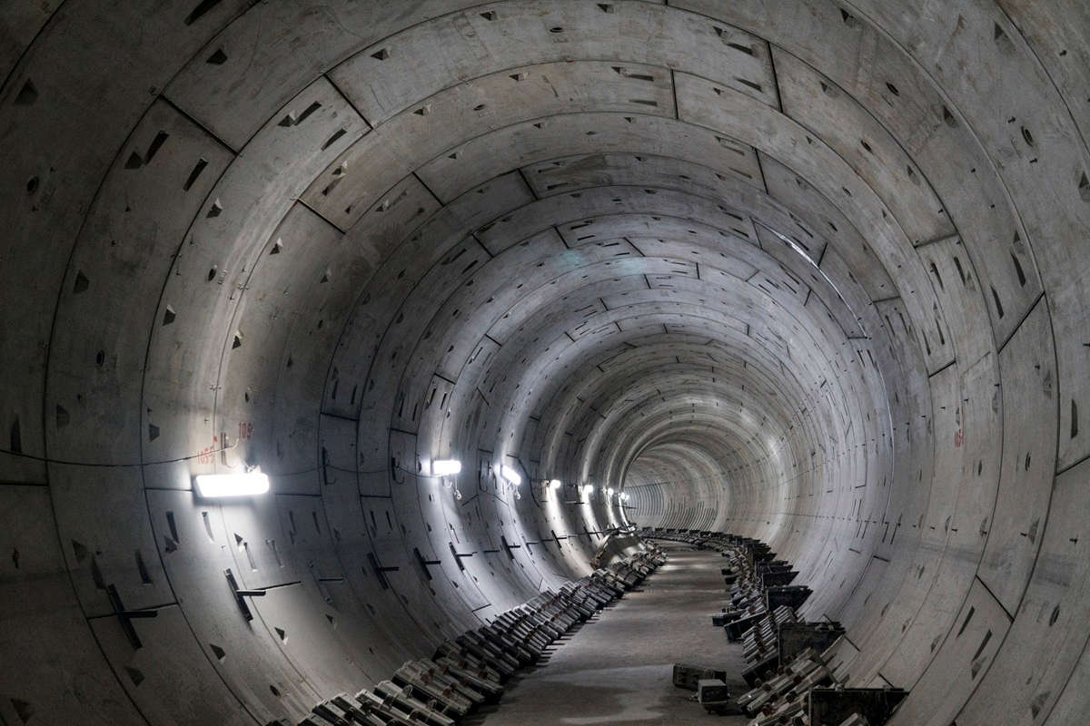
Mount Baker Ridge Tunnel (MBRT) and Mercer Island Tunnels (MIT), form a portion of I-90 freeway between Seattle, Washington and Bellevue, Washington. The tunnels include three general purpose lanes in each direction and a reversible two-lane center roadway. As part of Sound Transit’s East Link Project, the center roadway will be converted for light rail transit operations while modifying the eastbound (EB) and westbound (WB) roadways. Modification to EB and WB roadways will lead to the addition of new HOV lanes in each direction by reducing lane and shoulder widths. As a result of these modifications, the risk profile with respect to traffic incidents and fires prompted an upgrade of the tunnel emergency systems, including automatic fire detection and emergency ventilation.
Computational fluid dynamics (CFD) analysis determined that the previous fully transverse ventilation system for MIT was unable to maintain tenability during fires involving heavy goods and flammable liquid cargo. To mitigate risks associated with such fires, a longitudinal ventilation has been developed and validated using CFD. This scheme required upgrade and reconfiguration of previous fans and air distribution to deliver all supply air into the tunnels near the entrance portals through a Saccardo nozzle and to draw all exhaust capacity near the exit portals. Longitudinal ventilation options such as impulse fans and mini-nozzles at the previous supply ports were considered but the Saccardo nozzle was chosen due to its performance, relative cost, reduction in additional equipment and control simplicity.
This article details key aspects of retrofit.
Previous Transverse Ventilation

Figure 1 MIT – Previous fully transverse ventilation scheme (supply mains in blue, exhaust mains in red)
The previous fully transverse ventilation scheme for MIT is shown in Figure 1. In such a scheme supply air is introduced at low level into the tunnel via supply ports 0.15 m high by 0.76 m wide, located on roughly 2.4-m centers along the length of the tunnels. Supply air is delivered through duct mains above the roadway ceiling. The duct main splits into two sections: one feeding the western half of the tunnel and the other the eastern half. Distribution from the main duct to the supply ports is via fiberglass run-outs which drop down within the south tunnel walls.

Figure 2 MIT – Tunnel ventilation building and fan arrangement (supply in blue, exhaust in red)
The main exhaust ducts for each tunnel are located above the roadway ceiling and similar to the supply splits into two sections – one exhausting the western half and the other the eastern half of the tunnel. Air is exhausted at high level via penetrations, measuring 1.0-m wide and 0.3-m long, through the concrete ceiling panels located on roughly 2.4-m centers along the length of the tunnels. A ventilation building above the roadway near the crests of the tunnels houses centrifugal fans, three supply fans (SF) serving the EB roadway and three SF serving the WB roadway. Centrifugal exhaust fans (EF); three serving the EB roadway and three serving the WB roadway; are also located in the common fan building as illustrated in Figure 2. Table 1 summarizes the previous equipment serving the EB and WB MIT roadways.
Upgraded Longitudinal Ventilation
The viability of a longitudinal ventilation approach is incumbent on limited risk of traffic congestion within the tunnels such that vehicles downstream or “ahead” of the incident will be able to continue out of the tunnel. This allows the tunnel to be divided into two zones – upstream of the fire incident where tenable conditions are maintained due to prevention of back-layering and downstream where conditions would likely be untenable.

Table 1 Supply and Exhaust Fan Information for
EB and WB MIT
A longitudinal ventilation scheme within MIT is accomplished by reconfiguring the previous fans and air distribution elements such that ambient air is directed towards and delivered into the tunnel near the entrance portals, at a shallow angle (20º) and high velocity (30 m/s), through a Saccardo nozzle.
Additionally, all exhaust capacity is drawn from near the tunnel exit portals. This is designed to generate a venturi action that induces airflow from the portal to the other end of the tunnel. Momentum exchange between the high velocity jet and induced flow from the entrance portal will cause a net longitudinal airflow in the direction of traffic from “entrance” to “exit” in the tunnel. Average velocities in the tunnel are required to be at or above a critical velocity thus preventing back-layering of smoke to tunnel occupants upstream of fire.

Figure 3 (a) Previous transverse ventilation scheme, (b) Retrofitted longitudinal ventilation scheme for EB and WB roadways
A schematic representation of key elements that accomplish the longitudinal ventilation scheme by retrofitting the previous transverse ventilation scheme for the MIT roadways is shown in Figure 3.
The following changes to the existing equipment and air distribution means are required to implement the longitudinal ventilation system as conceptually described above:
- Upgrade supply fan wheels and motors for increased capacity and pressure (Table 2).
- Reconfigure supply ducts to direct all supply toward the entrance portal (Figure 3(b)).
- Close or seal existing supply ports (Figure 4(a)).
- Modify dividers near the entrance portals to create supply plenums spanning the tunnel widths (Figure 4(a)).
- Incorporate Saccardo nozzles near the entrance portals (Figure 5(a)).
- Close or seal existing exhaust openings (Figure 4(b)).
- Modify dividers near the exit portals to create exhaust plenums spanning the tunnel widths (Figure 4(b)).
- Create large point exhaust openings near the exit portals Figure 4(b).

Figure 4 (a) Supply air duct and (b) exhaust air duct to plenum transition
Fan rooms for the outer roadways of MIT are located near the center of the tunnel (Figure 2), roughly 450 m from the entrance of either the EB or WB tunnels. As a result supply air needs to overcome pressure drop over a length of 450 m in the existing supply duct, at which point the airflow needs to be turned 160 degrees such that it discharges aligned with the direction of traffic within the tunnel.
Additionally, the air velocity needs to be increased from the duct velocity up to the desired 30 m/s discharge velocity. A principle challenge being that this needs to occur within the existing vertical limits of the ducts above the roadway (~2.4 m above the eastbound roadway and ~2.8 m above the westbound roadway).

Figure 5 (a) Saccardo nozzle schematic showing shape and effect of varying “teardrop” radius (b) scaled saccardo nozzle for EB MIT (c) scaled saccardo nozzle for WB MIT
It is proposed that the contraction and turn are combined into a single nozzle fitting. The proposed “teardrop” nozzle concept (Figure 5(a)) consists of two components: a semi-circular “scoop” (red) and the “teardrop” (green). The “teardrop” nozzle was arrived at after consideration of more complex shapes iteratively through numerical optimization, physical scale testing, and structural support design. assessments.
CFD modeling was undertaken to optimize the shape of the nozzle, accomplished by varying the internal radius (Rn,i) of the “teardrop” and to estimate fitting loss coefficients for use in pressure drop calculations. By modifying the radius of the “teardrop”, the ratio of the fitting inlet and discharge (Hinlet/Hdischarge) is varied, resulting in a gradual contraction throughout the turn as indicated in Figure 5(a). Pressure measurements were extracted from

Figure 6 Fitting (a) pressure drop (b) loss coefficient
the CFD modeling and plotted vs. the inlet to discharge area ratio to identify optimal geometries. The results indicated that near optimal configurations for the EB and WB tunnels occur at inlet/discharge ratios of 2.0 and 3.0 respectively, Figure 6(a). The resulting fitting loss coefficients were 0.14 and 0.11 for the EB and WB tunnels respectively, Figure 6(b). Physical scale model tests for EB MIT Saccardo nozzle (Figure 5(b)) and WB MIT Saccardo nozzle (Figure 5(b)) further optimized the fitting loss coefficients for pressure drop calculations.

Table 2 Estimated SF upgrades for Saccardo
nozzle ventilation
Fan operating points to achieve the necessary airflow at the required pressures for the proposed longitudinal ventilation scheme are summarized in Table 2.
Design Evaluation
The retrofitted longitudinal ventilation system was evaluated using the following approach:
Identify critical fire locations in the EB and WB roadways.
Determine critical design fire characteristics.
Establish performance criteria for evaluation of CFD modeling results.
Steady state CFD modeling for system sizing (configuration and flow rates).
Transient analysis without the effects of deluge system to determine minimum required airflow rates.
Transient analysis with the effects of deluge system to determine the thermal and momentum impact of droplets in airstream.
The principle criterion for evaluating the longitudinal ventilation scheme for MIT is the ability to achieve critical velocity within the tunnel. Critical velocities for the MIT range between 2.0 and 2.3 m/s. Flammable liquid cargo (FLC) vehicle fire with a linear fire growth rate of 20 MW/min and a maximum fire size of 40 MW was simulated using CFD at three fire locations for each roadway.
Critical fire locations included a fire located near the tunnel exit portal(s), a fire located at/near the crest of tunnel, and a fire near the tunnel entrance portal(s). Fire locations were chosen to assess the effects of tunnel gradient, curvature, vehicles upstream of the fire, and interactions at the portals. The CFD model accounted for ambient temperature, adverse wind conditions, tunnel and trapped vehicle surface roughness, cooling and drag effects due to droplets from sprinkler deluge system.
CFD Modeling Results

Table 3 Summary of CFD modelling results (SS – Steady-State, Tran. – Transient)
Steady-state and transient CFD modeling results summary is presented in Table 3. The minimum nozzle supply airflow to achieve critical velocity for all fire locations was ~240 m3/s for each tunnel. In one case without suppression, critical velocity was not achieved; with suppression, critical velocity is achieved for all fire locations.
The results in Table 3 also indicate how rapidly combustion products within the tunnels can be expected to be controlled once the system is activated.
Summary
This article presented a case study with proposed changes to the MIT roadway ventilation. The previous MIT roadway ventilation system was a fully transverse system. Upgrades are being undertaken to retrofit the previous fully transverse ventilation system to deliver all supply air into the tunnels near the entrance portals at a shallow angle and at high velocity. The critical component of the proposed system is installation of a Saccardo nozzle just inside the entrance of each tunnel. Two-dimensional CFD modeling was used to optimize the shape of the nozzle and estimate nozzle fitting loss coefficients.
Three-dimensional CFD modeling was carried out to verify the performance of the proposed longitudinal system for the MIT. Modeling considered fires at three locations along each of the EB and WB roadway tunnels to cover the range of challenges posed by the tunnel geometric characteristics, specifically the grade, cross-slope, and curvature. The three fire locations were near the entrance portals, near the exit portals, and at the tunnel crests. Parametric studies were undertaken considering both steady-state and transient models where configurations, flow rates, and operation of the deluge system were varied.
The results of the analysis showed that the minimum nozzle supply airflow to achieve critical velocity and maintain a tenable environment for all fire locations evaluated was ~240 m3/s for each tunnel. The retrofitted system maintains a tenable environment upstream of the 40 MW design fire for each fire location evaluated.
Representative results from the overall analysis were included in this article to demonstrate the efficacy of the proposed system. Accordingly, the feasibility of retrofitting a transverse ventilation system into a longitudinal system re-using large portions of the existing ventilation equipment has been demonstrated.
RELATED: Ventilation on the World’s Longest Railway Tunnel
Acknowledgements
The authors would like to thank Bob Josephson and Igor Maevski of Jacobs for support in this project. The authors would like to acknowledge everyone from HNTB and URS who were involved in this project for their contribution and Alden Labs for the scale model physical tests. The authors would also like to acknowledge the support of the project from Washington State Department of Transportation.
Jarrod Alston, PE, is an Associate Principal in Arup’s Melbourne office. Deepak Kandra , PE, is an Associate Mechanical Engineer in Arup’s New York office. Richard Potter, PE, is an Associate Principal in Arup’s New York office.

Comments are closed here.