Cellular Concrete: A Cushion Over A Fault Line
The San Francisco Public Utilities Commission’s (SFPUC’s) Hetch Hetchy Regional Water System serves on average 260 million gallons per day (mgd) of drinking water to 2.6 million people in the San Francisco Bay Area. The system is critical to the economic viability of the area and the public health and safety of the region’s population. Although the system has performed extremely well for nearly a century, it is vulnerable to seismic events as it crosses three of the United States’ most active faults: the San Andreas, Hayward and Calaveras faults. In 2008, the U.S. Geological Survey predicted that there was a 63 percent chance that a major earthquake could strike one of those three faults in the next 30 years.
SFPUC initiated the Water System Improvement Program (WSIP) and was approved by voters in 2002 to ensure water delivery following a major earthquake in the Bay Area. The WSIP is a $4.8 billion multi-year program that includes 83 projects spread across seven different counties. The WSIP includes a wide variety of improvements, including the addition of new water treatment, transmission (pipelines, tunnels, pump stations), and storage (dams, reservoirs, tanks) facilities. It is the largest capital program ever undertaken by SFPUC.
One of the largest undertakings of the WSIP was the Harry Tracy Water Treatment Plant (HTWTP) Long-Term Improvement Project. At $278 million, the project seismically upgraded the existing water treatment plant originally built in the 1972 to ensure that it could deliver up to 140 mgd of potable drinking water to customers within 24 hours following a major seismic event on the San Andreas Fault.
During geotechnical investigations performed in 2008 for the HTWTP Long-Term Improvement Project, it was determined that fault strands were located within the HTWTP site and could cause significant failure to existing facilities as a result of a major San Andreas seismic event. The fault strands were determined to be part of the Serra Fault System, a secondary fault located along the peninsula in San Mateo County. During this investigation it was also determined that the main branch of the Serra Fault System could experience a fault rupture when triggered by a major seismic event on the San Andreas Fault. It is believed that the Serra Fault, acting as a “sympathetic” fault, could actually deliver 20 percent of the lateral movement and ground shaking of a large San Andreas seismic event. Since the three main transmission pipelines from HTWTP –San Andreas Pipelines No. 2 (SAPL 2), San Andreas Pipeline No. 3 (SAPL 3) and Sunset Supply Branch Pipeline (SSBPL) cross the Serra Fault, SFPUC conducted a more in depth, concentrated geotechnical investigation to better understand the potential for damage to these pipelines.

Trench after cellular concrete placement
The results included following a fault trenching study that identified the fault’s location, depth and orientation as it relates to the transmission pipelines. The study indicated that all three transmission pipelines could rupture in sections crossing the Serra Fault, if the potential maximum offset of the Serra Fault occurred during a San Andreas seismic event. These findings led to the creation of the Peninsula Pipelines Seismic Upgrade (PPSU) project, which ultimately addressed the seismic upgrade of three specific locations where the transmission pipelines crossed the Serra Fault.
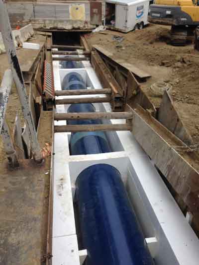
The new pipeline design at the fault crossings needed to address fault offset and ground shaking hazards. The design, performed by Kennedy Jenks Consultants under the direction of the SFPUC, consisted of a thick-walled steel pipe with mostly butt-welded joints that were encased in concrete, designed to resist the forces imposed by the Serra Fault. To address the fault offset, estimated to be approximately 12 to 24 in., Kennedy Jenks used a combination of conventional and unconventional materials to create pipe trenches that were stiff yet flexible, allowing the pipe to move. Gravel, sand, expanded polystyrene and cellular concrete were used to create a trench that would be strong enough to withstand the fault’s seismic forces, but flexible enough to allow the pipe to move.
In three sections of pipe, one of which directly crosses the fault zone and under a neighborhood thoroughfare, cellular concrete was used in combination with EPS Geofoam, sand, a 6-in. concrete slab, and a concrete encasement. The intention of this trench section was to absorb a fault offset without damaging the pipe. The two large diameter pipes (60 and 66 in. in diameter) were placed at depths ranging from 2 to 13 ft below grade at up to a 25% slope. The Geofoam was placed on each side of the trench and the pipe then backfilled with cellular concrete. The specifications called for a 30 psi cellular concrete (+/-5 psi). A Geofoam bulkhead was added by the contractor every 16 ft to divide the pipeline into 19 cells.
Installation Challenges
The obvious challenges in this application focused on the steep slope and highly fluid nature of fresh cellular concrete, equally difficult was the engineer’s need for a low strength of 30 psi (+/-5 psi). Cellular concrete was used here as a pairing with the Geofoam because its fluid-applied nature would provide a more intimate connection with the pipe. The low strength is intended to be as similar as possible to the Geofoam.
Throop Cellular Concrete was selected to provide the cellular concrete. Twenty-two pcf samples were cast and five-day breaks were used to forecast 28-day strengths. The existing project laboratory was unfamiliar with cellular concrete laboratory procedures and returned five-day breaks for 22 pcf cellular at 60 and 70 psi, which clearly indicated an error. It was not possible to be that strong with this mix. Cylinders were then taken to another lab (ENGEO Inc.) and breaks between 12 and 22 psi were obtained using properly calibrated low-strength testing equipment.

Cellular concrete placement in trench
Using the standard cure rate curve of cement, the breaks were on track for targeting 30 psi and the mix design was approved. The typical break spread was explained to the designers and they adjusted the specification to 25 to 75 psi (but still targeting 30 psi.)
For cellular concrete to achieve this ultra-low strength, the density must be lowered below the typical densities. Twenty-two pcf cellular was proposed based upon historical break information from the foam manufacturer and extrapolation of the typical density/strength curve. The concern with using 22 pcf cellular concrete quickly centered on lift heights and how deep such a low-density material could be poured each day. Cellular concrete has material limitations regarding lift heights based upon density and it was unknown how tall this mix would stand. A maximum of 2-ft lift heights were selected to start.
The contractor (Ranger Pipelines) skillfully installed the Geofoam on each side of the pipe along with Geofoam bulkheads every 16 ft. The steep slope of the pipeline required many lifts and formwork to hold in the nearly self-levelling cellular concrete. The team believed that the cellular concrete when poured in all the joints would seal the cracks and reduce or eliminate any leakage after one or two applications. Unfortunately this did not work very well; leakage was observed through some of the foam joints even during the fourth and fifth pours. It was believed that by walking on the foam, the newly created cement seals were being damaged. After the first and second placements of 2- ft lifts, it was observed, in the majority of the cells, the cellular concrete was leaking and possibly collapsing. Many cells contained less than 50 percent of the placed lift height. In order to strengthen the mix and stabilize the installed product, the team increased the density to 25 pcf, knowing this would also increase our test breaks.
After the fifth pour, a change of plans was needed to eliminate the leakage. There were multiple options evaluated. Ultimately an accelerator was added to the mix to quickly set the material. This worked perfectly and stopped the leakage and/or collapsing by rapidly solidifying the material. This solution did not provide the answer to the onsite debate of leakage vs. collapsing, but it solved the problem.

Final cellular concrete placement
in trench
The next challenge was to form the top to hold the material in the trench at the 30% slope required. The contractor placed plywood forms across the top with large pipe weights on the edges and sprayed expanding foam as a gasket. This worked well in areas where 2-ft lifts were systematically installed. Higher lifts caused a few failures.
Test breaks were returned from the laboratory with the 22 pcf averaging 29.1 psi and the 25 pcf averaging a surprising lower 28.5 psi. Everybody was ecstatic how close the breaks were to the original target strength of 30 +/- 5 psi.
In the end, SFPUC met design requirements and used an innovative tool in a very complex environment. With these lessons learned, it is an important reminder to always consider new innovative tools to build and deliver the best possible projects.
Scott Taylor, P.E., MBA, is President of Throop Cellular Concrete. Heather Manders, P.E., is Assistant Engineer, and Joseph Liu, P.E., is Project Construction Manager for SFPUC.

Comments are closed here.