Innovations in Precast Concrete Segmental Linings: Case Studies from Around the World

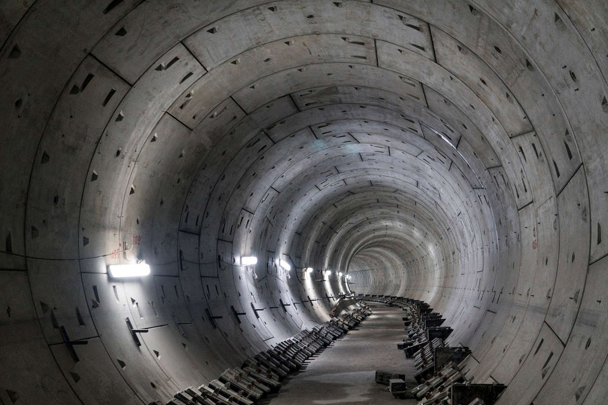
Constructed segments on the San Fransisco Central Subway Project
Since their introduction, precast concrete segmental linings have continued to develop and evolve. In this article, Jon Hurt, Tunnels Practice Leader at Arup, provides an overview of four projects, highlighting ongoing innovations to meet project challenges. The continued trend toward steel fiber reinforced concrete (SFRC) linings is particularly apparent, and the projects include the first metro project in a seismic zone in the western United States to use steel fibers, 26 miles of SFRC linings under London, their first use as a permanent lining in South East Asia and in a large-diameter tunnel in Brisbane, Australia.
Central Subway, San Francisco, Calif.
The SFMTA C1252 Central Subway project consists of approximately 2 miles of surface and subsurface rail that will extend the Third Street Light Rail in a Northwest-Southeast link through the center of San Francisco. The San Francisco Municipal Transportation Agency project will link Chinatown to the downtown and south of Market Street areas of San Francisco, including AT&T Park. Contract 1252 includes construction of the 500-ft launch box, retrieval shaft, approximately 1.7 miles of twin tunnels, and five cross passages.
Barnard-Impregilo-Healy JV (BIHJV) pursued the project, with Arup providing pre-bid assistance. BIHJV was the successful low bidder at $225 million and was awarded the contract in December 2010. The first TBM launched in July 2013 with the second launched in October. Mining is scheduled for completion mid-2014.
Segmental Lining
The contract provided a fully designed segmental lining. However, the owner allowed a redesign of the segmental lining such that the temporary and construction loads were taken through a combination of steel fibers and high-strength welded wire reinforcement, while maintaining the full design capacity to address the permanent loads. The segment geometry was also modified to a 5+1 system with a single 22.5 degree trapezoidal key and five 67.5 degree segments, four of which are rhomboidal and one trapezoidal counterkey. The contract provided a 4-ft ring width, together with a 1.6-in. taper, which was required due to the tight curves (450-ft min. radius) at select locations along the project alignment. A 5-ft ring with a 1.1-in. taper was introduced for the straighter sections along the majority of the alignment. Concrete cylinder strength was specified as 6,000 psi and polypropylene fibers were used to control spalling in the event of a fire at a dosage rate of 1.7 lbs/cu yd.
Arup worked with BIHJV and the segment manufacturer to complete the design and incorporate changes to suit the manufacturing process and construction process. Segments were cast in a designated factory in Sloan, Nev., by Precast Management (the same supplier for the rings on the Lake Mead Intake No. 3 Project). Stationary molds are used with ambient concrete curing.
Innovations
Steel Fiber Reinforced Concrete: The reinforcement in the segments was redesigned to change from a complete rebar cage with 60 ksi (410 MPa) steel, to a hybrid arrangement of steel fiber reinforced concrete (SFRC) together with a lighter rebar cage of 80 ksi (550 MPa) steel. The tunnel passes through both soft ground and moderately strong rock, and is in a highly seismic area. Within the constraints of the time available for design and approvals on an active construction project, the hybrid approach was selected to provide the benefits of SFRC while providing rebar reinforcement to resist the seismic load case. Though the use of fibers does allow for less rebar to be used, U.S. design codes do not allow designers to combine the benefit of fibers and reinforcement in the same calculation, and thus the rebar has to be designed to take the full structural loading on the tunnel. For temporary loading related to the ram forces from the TBM, joint rotation and segment bursting forces, fibers can be considered, allowing the rebar for the ram and joint areas to be reduced. Reinforcement quantities for the redesigned segments was 159 and 153 lbs/cu yd (94 and 91 kg/m3) of traditional reinforcement for the 4- and 5-ft (1.2- and 1.5-m) segments, respectively, with an additional 45 lbs/cu yd (27 kg/m3) of high-performance Bekaert Dramix 65/60-BN fibers. Costs of a traditionally rebar-reinforced segment and the hybrid variety were compared and shown to be more-or-less equal, but the use of fibers has previously been demonstrated to result in lower segment damage during installation, improving durability and reducing repair costs. To date very little damage to the segmental linings has been seen in the sections of completed tunnel.
Footed Gasket: The segments utilize cast-in gaskets that are fitted into the segment mold prior to casting. The footed gasket anchors the gasket to the concrete without the need for additional handling, use of adhesives and additional equipment to compress the gasket into place. This saves the number of steps needed to fabricate the segments. One of the challenges for the incorporation of the footed gasket was addressing concerns over repairs if a section is damaged. To address this, BIH worked in close cooperation with Datwyler to assemble a comprehensive repair plan for the gaskets in order to get approval from the owner.
Dowel Connections: The specifications required the circumferential connectors to resist 21,000 lbs (95 kN) of pullout, with Soffix-80 high-strength dowels used. These dowels have high-relief ribbed connections, requiring all the tolerances due to packer thickness and compression and mold and fabrication to be accounted for in order to provide the perfect fit. Because the stations are to be constructed after the tunnels are completed, a method to easily separate the segment rings was required. This meant using a fiberglass core in the dowel connectors that could be saw-cut instead of the steel core in these sections.
Segments by Train: The segments are travelling 400 miles by rail from the casting plant in Nevada to the job site. Trials were performed before casting commenced to confirm the stacking arrangements and verify that the segments would not suffer from vibration damage.
Crossrail, London, U.K.
Crossrail is Europe’s largest infrastructure project and will cost £14.8 billion ($24.3 billion). It will deliver a 118-km (73-mile) rail line that will link Maidenhead and Heathrow in the west with Shenfield and Abbey Wood in the east via 21 km (13 miles) of twin-bored tunnels under London, a total of 42 km of tunnel. Crossrail will begin services in the central section in 2018. When completed Crossrail will transform rail transport in the capital, bringing an extra 1.5 million people to within 45 minutes of London. Crossrail will increase the capacity of London’s rail-based public transport network by 10 percent. There will be 37 Crossrail stations including eight new underground stations.
The construction of the TBM tunnel is divided into three main contracts: Drive X (C300), Drives Y, Z & G (C305), and Drive H (C310). All those mentioned drives have the same segment configuration. Arup, within the Arup-Atkins Joint Venture (AAJV) has been appointed as the TBM tunnel’s segment lining designer since 2006 (preliminary design stage), carried out the complete design and detailing of the segment lining and is currently providing construction phase services during the construction of TBM tunnels.
Segmental Lining
The 6.2-m (20.3-ft) internal diameter bored tunnel linings are precast concrete segments reinforced with only steel fibers for the typical sections. Rebar reinforcement was used for only two cases – locations where high unbalanced loading condition is expected such as under bridge abutments, and under sections of floating slab track where point loads from the bearing could cause punching shear through the segment. The segments are 300 mm thick (11.8-in.) and 1.6 m (5.25 ft) long with 7 segments + 1 key in each ring. C300 and C305 adopted left and right tapered rings to allow the key segment to always be placed above the tunnel axis. C310 adopted a universal ring. Spear bolts are used on the radial joints and dowel connections on the circle joints. Segments were cast in a separate factory by each tunneling contractor. C300 used foil blanket curing, C305 adopted steam curing (Carrousel system), while C310 used a combination of both. Due to the use of steel fiber, the use of poker vibrators was not allowed and the molds were vibrated by attaching vibration motors to the mold. For stations where TBM drives through the platform area prior to the sprayed concrete lining (SCL) enlargement construction, a special 1.0-m long temporary segment has been introduced to match with the typical 1.0-m advance rate of top-heading, bench and invert excavation of SCL platform tunnel. Since the temporary segments will be removed during the SCL enlargement of the platform, bolts were used for both circle and radial joints to facilitate the dismantling sequence of the segment.
Innovations
Steel Fiber Reinforced Concrete: The finite element code LS-DYNA was used for the calculation of joint bursting stresses at the joint of Crossrail segment. The rheological model employed for SFRC was termed the Winfrith 58 material model. The parameters of this model were established to simulate the tensile splitting behavior by estimating the energy/area under the stress-strain envelope derived from beam testing. The model used at the beginning of the design stage was calibrated against joint tests performed for the Channel Tunnel Rail Link (CTRL) project but additional test data became available from prototype joint test studies carried out for the Thames Lee Tunnel. Finite element analysis of the Thames Lee test data using the Winfrith 58 model indicated that the FE model tended to slightly underestimate the ultimate load capacity of the joint, but more importantly the model did not accurately predict the crack patterns observed in the prototype test segments at ultimate load. The Thames Lee prototype tests indicated that the initial crack pattern was a tensile splitting failure within the end body of the segment, but as the load developed a wedge of concrete was driven into this initial split.

Contech Precast Pte. Ltd. segment factory for contract C933.
The final failure occurred as a complex interaction between tensile splitting and shear failure surfaces. The analysis also indicated the importance of ductility of the SFRC, as the load capacity increased if the joint bearing surfaces could locally crush down and widen in a controlled manner, causing the width of the bearing area to increase with a consequent reduction in tensile splitting forces. Accordingly, the formulation of the Winfrith 58 model was modified to include duel tension and shear failure criteria. Procedures were also developed to calibrate the material model from beam tests performed in accordance with BS EN 14651 and split cylinder tests in accordance with BS EN 12390-6. Back analysis of the Thames Lee tunnel data using the revised material model showed close correlation with the test data not only in regard to ultimate loads predicted but also between the crack patterns observed. The modified Winfrith 58 material model therefore afforded increased confidence in the calculation of the joint bearing capacity determined for the segment design.
During manufacture, steel fiber performance was tested using the flexural beam test. It was found that the flexural beam test result gives a relatively large scatter compared with the compressive and tensile splitting tests, particularly for the fR1 values. The larger scatter sometimes pulled the estimated characteristic strengths below the required minimum performance target. On the other hand, the cube and splitting strength generally had consistent and above-specified test results. The modified material model was used to reassess the segment joint capacity, and to establish the acceptability of batches of segments based on the characteristic flexural strengths measured from the segment production tests. From the reassessment results, maximum overburden that those segments were able to withstand was determined. This was to allow AAJV to identify zones along the alignment that those segments could be safely installed, instead of rejecting large quantities of segments.
Downtown Line, Singapore
Singapore’s 42-km (26-mile) long DOWNTOWN LINE (DTL) will connect the northwestern and eastern regions of Singapore to the Central Business District and Marina Bay area by 2017. DTL will be the fifth Mass Rapid Transit (MRT) Line in Singapore and will include 34 stations, 10 of which will interchange with the existing MRT system. When completed, the Downtown Line will be Singapore’s longest automated underground line.
The project is sponsored by the Land Transport Authority (LTA), which is constructing the route in three stages (DTL1, Central Area. DTL2, Northwestern/Bukit Timah. DTL 3, Eastern). For each stage of the works the route is subdivided into a series of contracts. Arup was appointed by the LTA to provide Architectural/Engineering Consultancy Services for Package A, consisting of 4.3 km (2.7 miles) of twin bored tunnels and associated station structures for the proposed Downtown Line Stage 3 (DTL3).
Package A is divided into five construction contracts (three tunnels and two stations):
- C937 – River Valley Station and associated tunnels in each direction to DTL1 C909 and Bencoolen Station
- C936 – Bencoolen Station
- C935 – Sungei Road Station and associated tunnels to Bencoolen Station
- C933 – Jalan Besar Crossover Box and associated tunnels in each direction to Sungei Road Station and Kallang Bahru Station
- C932A – Kallang Bahru Station
Arup was the egmental lining designer for contracts C933, C935 and C937 and continues to provide technical support to the LTA during the construction phase.
Segmental Lining
Two types of pre-cast segment linings were used for the permanent structure of the bored tunnels. For C935 and C937, a traditional bar reinforced segment was adopted and for C933 a steel fiber reinforced segment was proposed and adopted by the LTA. Both segmental linings have a thickness of 275 mm (10.8 in.) and are 1.4 m (4.6 ft) long. A 5+1 segmentation (three ordinary segments, two top plates/counterkeys and one keystone) is used for the traditional bar reinforced segments and a 7+1 segmentation (five ordinary segments, two top plates/counterkeys and one keystone) is used for the steel fiber reinforced segments. The number of segments was increased for the steel fiber design to minimize potential damage during handling and installation. Left and right tapered ring has been adopted and the key segment is always inserted above the tunnel axis. Typically a +/- 20 mm (0.79 in.) taper has been adopted to ensure a 300 m (984 ft) horizontal alignment radius could be achieved. Segments are connected by spear bolts on the radial and circumferential joints, and these fixings are left in the tunnel in the permanent case.
For the C933 steel fiber segment design, all segments were precast in a purpose-built plant in Jurong, Singapore, using a carousel system. Concrete is compacted using external vibrators mounted on the mold, equivalent to the vibrating table method. After casting, the segments are completely sheeted to prevent loss of moisture from the concrete. The segments are then epoxy coated and transported to a storage area before being stacked using timbers to prevent damage.
Innovations
Steel Fiber Reinforced Concrete: In the early planning of Singapore Downtown Line 3 MRT, LTA saw the potential valuable benefits of steel fiber reinforced concrete (SFRC), a new alternative material to conventional steel bar reinforced concrete (RC) that would bring productivity and innovation to the Singapore construction industry. Research and testing in collaboration with Nanyang Technological University (NTU) was carried out to develop performance-based design comparable to Singapore Standards. This is the first utilization of SFRC material for permanent structure in Singapore and South East Asia. LTA’s design criteria and Singapore Code of Practice consider segmental linings to be short column subject to bending moment and axial load. In order to enable approval of SFRC in Singapore from relevant authorities, a detailed design was prepared comparing existing SFRC segmental lining designs and industry guidance to Singapore Standards (SS CP65); defined minimum performance criteria developed based on specific testing; and mix testing carried out in association with the contractor (Penta Ocean Construction Co. Ltd.) and the fiber supplier (Maccaferri). Arup carried out finite element modeling of segment joints to evaluate SFRC joint bursting behaviors on both the radial and circumferential joint. To ensure segments were not damaged during TBM build, a TBM thrust limit was agreed with LTA and the contractor based on project specific material properties. Utilization of SFRC for the C933 segmental tunnel lining resulted in a cost and labor efficient, sustainable lining material. In the upcoming Thomson Line MRT Tunnels, LTA and Arup are continuing to collaborate, improving SFRC design in Singapore based on current DTL3 experiences.

At 11.34 m internal diameter, the mainline TMB tunnels for the Brisbane Airport Link Project contain the largest pure SFRC segmental tunnel linings in the southern hemisphere and possibly the world.
Brisbane Airport Link, Brisbane, Australia
Brisbane Airport Link is a 6.7-km (4.2-mile) toll road, mainly underground, connecting Brisbane city to the northern suburbs and the airport precinct. It is the primary part of Australia’s largest transport infrastructure project, the $4.8 billion (AUD) ($4.2 billion US) three-projects-in-one, Airport Link, Northern Busway and Airport Roundabout Upgrade. Airport Link consists of approximately 5 km (3.1 miles) of twin bore mainline tunnel, multiple tunnel ramps, extensive cut-and-cover structures and significant surface works. On completion, it will be Australia’s longest road tunnel with a total of 11 km (6.8 miles) of mainline tunnel and tunnel ramps. The general arrangement of the mainline tunnel works on the project (excluding cut-and-cover) comprises mined tunnels between Bowen Hills and Lutwyche, TBM bored tunnels between Lutwyche and Toombul and mined caverns at Kedron (to facilitate connection of the Eastbound Onramp and the Westbound Off-Ramp with the TBM tunnels). The mainline tunnels are connected to the surface via cut-and-cover structures at Bowen Hills (Southern Connection) and Toombul (Eastern Connection), and via mined tunnel ramps and cut-and-cover structures at Kedron and Lutwyche (Kedron Connection).
Two major civil engineering contractors, Thiess and John Holland, formed a joint venture (TJHJV) to design and construct the Airport Link project. Engineering design consultancies Arup and Parsons Brinckerhoff formed a joint venture (PBA) to design the project on behalf of TJHJV.
The TBM tunnels were constructed with two 12.28 m (40.3 ft) EPB TBMs through a mixture of soft ground mixed face conditions and rock varying from highly weathered sedimentary to competent tuff. Each TBM drive commenced at Toombul (Eastern Connection) and proceeded toward the Lutwyche caverns, where the TBMs were buried on completion of TBM tunneling. The total length of each TBM tunnel (including the Kedron Cavern traverse) is approximately 2.4 km (1.5 miles) and, with an outer diameter of 12.14 m (39.8 ft), are the largest diameter TBM tunnels to be designed and constructed in the southern hemisphere.
Segmental Lining
The TBM tunnel linings were assembled from left and right universal rings. Although universal rings were used, both left and right rings were cast to enable the key to be maintained above axis for majority of the ring build. The internal diameter of the segmental lining was 11.34 m (37.2 ft), segment thickness was 400 mm (15.7 in.) and ring length was 2.0 m (6.6 ft). A 9+1 ring segmentation comprising seven rectangular segments, two counterkey segments and one keystone segment was adopted for the rings.
Innovations
Steel Fiber Reinforced Concrete: The primary new technologies/material used in the segments was steel fiber reinforced concrete (SFRC). Approximately 65 percent of the mainline TBM tunnel extent was constructed from pure SFRC segments, 25 percent from SFRC segments with additional rebar at the radial joints and the remainder from conventionally reinforced segments. At 11.34 m internal diameter, the mainline TMB tunnels for the Brisbane Airport Link Project contain the largest pure SFRC segmental tunnel linings in the southern hemisphere and possibly the world. The use of SFRC, rather than conventional bar reinforced concrete, is known to provide significant benefits for long-term durability and maintenance of segmental tunnel linings. However, the structural capacity of pure SFRC is typically lower than that of conventionally reinforced concrete for segments of the same thickness. The circumferential joints of the lining are subject to concentrated loading from the TBM ram load. The TBM ram thrust loading was developed by 19 pairs of thrust cylinders and applied to the circle joint by 19 equally spaced, 900 mm (35.4 in.) long x 360 mm (14.2 in.) wide ram shoes. For the 9+1 segmentation adopted this resulted in two shoes per segment and one shoe per key. The maximum installed thrust was approximately 89 MN. The typical operational thrust varied up to approximately 60 MN. The design analysis revealed that as the applied ram thrust approached maximum installed, splitting at the circle joint face between adjacent ram shoes rather than bursting beneath ram shoes was the limiting case for the standard SFRC (Type 1) segments. A sensitivity analysis was then carried out to determine the limiting ram thrust to control splitting. In the most onerous case, the required thrust limitation still permitted 87 percent of the maximum installed thrust to be applied.
Many thanks to my colleagues Luis Piek, Hyuk-il Jung, Rob Harding and Owen Francis for their contributions to this article.

Comments are closed here.