Tunnel Shaft Dewatering Dealing with Stratified Soils Below the Water Table

However, if the shaft is below the water table and the soil structure is stratified, the tunnel shaft is advancing “against the grain” and “in the wet,” which presents critical problems. If wet soil material is allowed to flow in at the dig level, voids will develop behind the shoring. This can result in “soil piping,” which can result in subsidence. At its worst, the shaft could collapse or even flip in the excavation, resulting in possible injury to workers and ruining the site and surrounding structures. At its best, the voids can be pumped full of grout and serious damage avoided. But inspectors don’t take kindly to voids behind the plates, filled or not, and can shut the job down until a plausible plan of action is created.
To avoid such possibilities, before the bid, dewatering contingency plans should always be included in the schedule.
The conventional dewatering remedies installed outside the shaft include the following:
- Deep wells if the soils are permeable from top to well below the bottom of the shaft
- Vacuum-assisted deep wells for the same reasons but when sands are very fine or clayey
- Vacuum-assisted wellpoints if the shaft is shallow, no more than 20 ft deep, or the wellpoints can be benched down below the natural ground surface outside the shaft
- Eductor wells if the soil is very tight but will drain
Concrete soldier piles or a grout curtain in very low permeability soils when the wet soils won’t drain freely.
If the soil is mostly stable and doesn’t flow, sumps and vacuum-assisted wellpoints are effective inside the shaft if there is room.
In known stratified soils, the potential for being stopped dead in your “wet” tracks has to be faced before digging in the first ring of shoring. The usual practice is to ring the shaft with deep wells set close to the shoring to pre-drain the soil, hoping that the well bore hole drilled through the strata will drain the water to the bottom of the well. The fallacy is that the bore hole is not a hole because it is filled with filter sand. The second fact is that water will always take the path of least resistance. So, as the shaft is advanced toward an impervious, usually clay, strata the ground water sees the shaft as a very large well. It finds it easier to flow to the open excavation rather than abruptly turn 90 degrees and fight its way through the bore hole filter sand. Like a weather pattern, the excavated shaft is the low pressure system and the ground water is the high pressure system.
Contingency planning when building a tunnel shaft construction schedule is usually dependent on the construction easement. Usually the easement doesn’t allow the needed space to install much of an exterior dewatering system. Because of this common fact, deep wells are often chosen and drilled very close to the shaft regardless of what the soil borings say. Unfortunately in stratified soils, deep well traits cater to logistics but not to the goal of dewatering the shaft. Dewatering planning is critical to a successful construction schedule and it is prudent to engage the help of a knowledgeable dewatering firm with a history of successful tunnel shaft dewatering projects for advice. The past successes should include projects that required quickly adjusting to abrupt changes in soil conditions or to uncovered water sources like leaky water mains or abandoned pipelines. Dewatering technique hinges on dealing with, and anticipating, unknown conditions and quickly modifying the system to address them. This includes contaminated ground water or water with naturally high levels of soluble iron or calcium.
Assuming that the exterior dewatering methods are not going to eliminate the ground water threat, and soldier piles and grout curtains are out of the question, the only remaining remedies have to be installed from inside the shoring.
This can be done without taking up much more room than the walers. Hopefully, accurate soil borings of the site exist that show the elevations of the impervious strata, the types of sands sitting on those strata and the thickness of each water-bearing layer. If there aren’t adequate soil borings – drill some! If you question the soil borings provided – get some more! It’s good insurance. Knowing what changes are coming up allows time to install the dewatering system and avoid being stopped by flowing water and mud. And, production advances steadily downward.
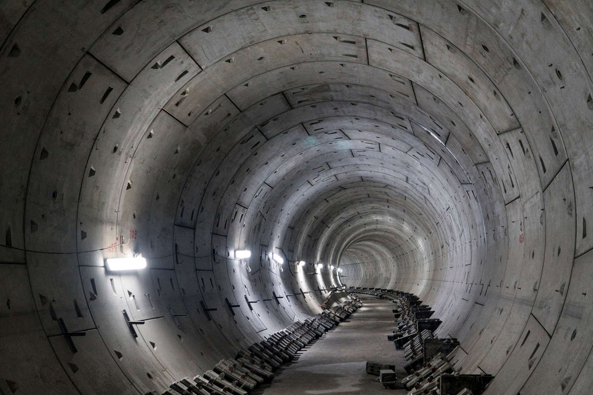
On sites with multiple impervious strata, a series of vacuum systems can be planned, each being installed through the shoring just below the last impervious strata into the next water-bearing layer. (See the figure.) The vacuum-assisted wellpoints are installed at an angle through or under the last ring of liner plates or boards. The collection piping or header can be set on a waler or hung from the shoring.
Usually vacuum-assisted systems are hampered by suction lift limitations. This is not necessarily the case when installing reclined vacuum-assisted wellpoints into confined aquifers. The trick is to install the water pump below the header line and the vacuum pump at the ground surface out of the way. This is done by installing a vertical PVC pipe from the top of the shaft to the bottom. The header pipe at each layer is connected to the vertical pipe as the shaft excavation advances. An advantage of this method is that the vacuum gauge reading can be very low, 5 to 8 in. of mercury (Hg). This allows the vacuum pump to extract vapor from the confined aquifer and create a lower pressure zone away from the shoring outside the shaft. The suction tips of the wellpoints have to be sitting in the deeper strata at the bottom of the sandy soil like a vacuum cleaner wand.
This can be done in multiple layers as the shaft is advanced with each vacuum header system connected to the same vertical pump casing. The pump size has to be calculated based on the total volume of water that will be pumped so that the vertical casing pipe can be sized large enough to fit the pump. A 5-hp contractor’s style submersible pump will fit into an 8-in. PVC pipe, but a 15-hp contractor’s style submersible pump will need a 12-in. PVC riser pipe. There is no limit to the number of horizontal header systems that can be connected to a vertical pump casing.
Multiple vacuum pumps or large single vacuum pumps can be used to draw more air for greater effect. Using the vacuum pumps as air strippers also keeps them cool, reducing maintenance requirements. Usually, two vacuum pumps combined will total 30 hp or less. This type of dewatering system will not be a massive burden on the project.
To make this system even more appealing, modern vacuum-assisted wellpoints are made of flexible polyethylene piping with geotextile fabric screen on an internal framework. This style is very rugged, takes up less room and operates very efficiently. Also, in most cases, they can be abandoned in place. Each is very light and can be shipped to the jobsite in a roll via overnight delivery services.
In conclusion, with good information on the site soil conditions, surrounding water shed influences, existing utilities with potential leaks and easement limitations, a combination of dewatering techniques can be planned well in advance. Setting milestones in the schedule and a “go, no go” punch list will allow movement from one contingency plan to the next without shutting down the schedule. Plan for the worst and hope for the best! Also, have dewatering equipment stockpiled nearby. Better to pay the standby rental rate than to carry the whole job overhead during a shutdown while you wait for the equipment to arrive.
Tom Minihan is vice president of Griffin Dewatering. He has over 40 years of dewatering experience and has designed and manufactured dewatering equipment and installation systems, holding several patents on air-water separation systems.

Comments are closed here.