Tunneling Challenges on the City of Houston’s Northeast Transmission Line

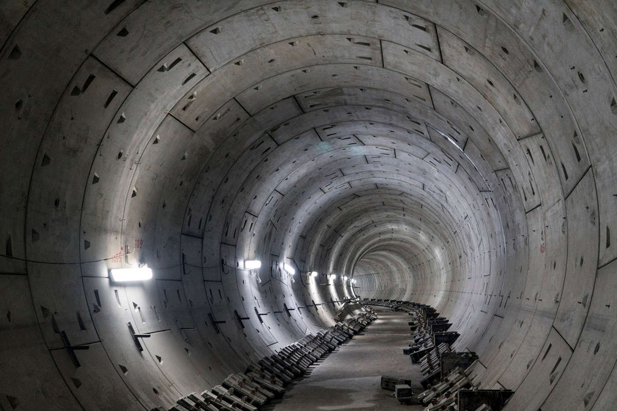
Project team members observe shaft preparation next to the 137-in. diameter head EPBM. The IH-69 bridge crossing location can be seen in the background.
Ten years ago, the City of Houston and regional partners began planning an ambitious pipeline project to convey up to 365 million gallons per day of treated drinking water 16.5 miles across the urban landscape. The mostly 108-in. diameter pipeline, dubbed the Northeast Transmission Line (NETL), is an integral part of the overall regional water plan to meet the 2040 demand and meet groundwater use reduction mandates. It originates near Lake Houston, where it will receive treated water from the currently under-expansion Northeast Water Purification Plant. From there, it runs generally west to I-45, with various take-points and interconnects along the way.
The project is split into 13 contract segments, and approximately eight of the 16.5 miles of the pipeline (six segments) are installed to date. Lockwood, Andrews, and Newnam, Inc. (LAN), a national planning, engineering and program management firm, serves as the overall project program manager and design engineer on 3 segments. One of the segments designed by LAN – a 1.2-mile segment of 108-in. water line along city easements – required five tunnel crossings:
- 1,150-ft long crossing of IH-69 at a bridge section and adjacent businesses
- 150-ft long crossing of an active Union Pacific Railroad (UPRR) track, 42-in. water line, and 72-in. sanitary sewer
- 250-ft long crossing of a TxDOT Farm-to-Market Road
- 170-ft long crossing of a City roadway, petroleum pipeline corridor, 66-in. water line, and high-tension overhead power lines
- 265-ft long crossing of a City major thoroughfare, gas main, and 60-in. storm sewer
Highest Risk Tunnel
The 1,150-ft long crossing of IH-69 posed the greatest challenges. The crossing occurs along Aldine Bender Road/TxDOT FM-525, where IH-69 consists of 15 elevated main lanes and eight frontage road lanes. The tunnel alignment passed between bridge columns with 30-ft clearance at a depth of 20-ft to the crown. Soil conditions varied along the alignment, with the worst being directly within the footprint of half the bridge and the northbound frontage road. In this area, the soil within and around the bore consisted of relatively clean, fine-sand as well as silty-sand under the groundwater table. These instable soils and alignment proximity to the bridge columns created the potential for impacting the bridge during tunnel excavation.
Design Strategy
The design focus was identifying solutions to mitigate risk to the bridge from construction that could feasibly be implemented within the project schedule and pass TxDOT permitting requirements. Two general approaches were considered: stabilizing the soil prior to tunneling and use of a pressurized face tunnel boring machine (TBM).
At this tunnel diameter (minimum 128-in. bore), suitable pressurized face TBMs are rare in the region, and procuring one was anticipated to require an unacceptable lead time. Instead, planners focused on strategies to stabilize the soil prior to tunneling with an open face machine. Dewatering was immediately taken off the table by TxDOT. The initial soil investigation and analysis indicated soil chemical grouts, such as sodium silicate and acrylate systems, could adequately stabilize the non-cohesive soils and reduce soil permeability. The design was finalized utilizing the soil chemical grout strategy with the requirement that excavation be performed using an open face TBM with face closure capabilities.
Construction
As a first step, the contractor, Harper Brothers Construction (HBC), was required to perform additional soil investigation in the tunnel zone and develop a detailed soil grouting plan. The evaluation identified additional zones of silty sand that are difficult to adequately permeate and stabilize with grout. Re-evaluation of the strategy indicated grouting was still viable, albeit with greater risk than anticipated. To everyone’s surprise, HBC indicated they could procure an earth pressure balance machine (EPBM) in time to meet the contract schedule. In lieu of grout, they proposed to utilize the EPBM along with casing pipe (instead of liner plate) and two intermediate jacking stations. After careful evaluation by LAN and the City of Houston, the contractor’s proposal was accepted. The tunnel was successfully installed from January to March of 2020. Monitoring of the bridge before, during, and after construction revealed no movement beyond natural fluctuations.

The HBC tunnel crew grouting the overcut behind the liner for the UPRR tunnel. Grouting was specified every 5-ft of liner installation or at least daily to prevent loss of ground.
Railroad Crossing
While only a short 150-ft length, the crossing of the UPRR tracks presented several design and constructability challenges. UPRR allowed for no more than ¼-in. movement of its tracks. Deepening the tunnel bore is one strategy to minimize the maximum settlement; however, in this case the crossing was congested with an existing 42-in. water line and 72-in. sanitary sewer. There was enough space to pass the tunnel between the existing lines at a depth of 14-ft to the crown, or alternately the alignment could pass under the sanitary sewer at a depth of 40-ft to the crown. It was strongly preferred to keep the tunnel to the shallower depth to avoid the extra shaft expense of deepening the tunnel. Analysis showed the shallower depth was feasible with good tunneling practices.
The tunnel was constructed by hand-mining within a shield and was lined using 4-flange liner plate. The tunnel face was stabilized using breast boards with partial coverage during excavation and full coverage during down times. Similar to TxDOT, UPRR did not permit dewatering in their right-of-way. However, when HBC ran into a sand formation during excavation, UPRR allowed for dewatering to stabilize the soil. The rails and surrounding ground were monitored daily before, during, and after construction to identify any excessive ground movement that could lead to a dangerous condition.
While no risk ever materialized for the trains, the conditions in the tunnel became dangerous while trains passed over due to vibration. Workers were required to stand on ladders to bolt the top sections of liner plate and excavate the top portion of the bore. UPRR assisted in keeping the conditions safe by reducing train speed during tunneling to limit the vibrations. The tunnel was otherwise completed without complication.
Project Completion
This 1.2-mile segment of the NETL was completed in October 2020 on schedule and under the original contract amount of approximately $36 million. The collaborative attitude between the City of Houston, LAN, and HBC allowed the team to successfully navigate the change in method for the IH-69 tunnel. As a lesson learned, bidding alternates for the tunnel methods would have made it easier to adopt the change. A proper balance of mitigating risk by specifying methods and safeguards and allowing contractor flexibility should always be provided as appropriate to each case. The overall NETL is anticipated to be completed by October 2022.
Michael V. Liga, Ph. D., P.E., is an associate and senior project manager at Lockwood, Andrews & Newnam, Inc. (LAN), a national planning, engineering and program management firm. He can be reached at mvliga@lan-inc.com.
RELATED: TBM Provides Versatility in Difficult Ground for Water Conveyance Tunnel In El Paso

Comments are closed here.