Down to Earth: Slurry System Planning for Low Gravity Solids
By Matt Wiggins
As tunneling projects expand in scale and complexity, managing the slurry system becomes a critical factor in overall project success. One often overlooked variable is the accumulation of low gravity solids (LGS), which can compromise excavation efficiency, increase wear on equipment, and disrupt fluid circulation. This article explores the behavior of LGS in civil tunneling applications and offers strategies to mitigate their impact using proper slurry conditioning and equipment design.
What are Low Gravity Solids
The term LGS refers to particles that have a specific gravity of 2.1-2.9. This is simply the amount of matter per unit volume within the geological particles, causing them to be slightly denser than water. When solids are added to a water-based fluid, some of the free water becomes attached to the solids by way of intermolecular forces; this is called adsorption. This decreases the amount of free liquid and increases the fluid’s viscosity. The amount of water adsorbed by a given quantity of solids is a function of:
- Particle size of the solids
- Reactivity of the solids
- Type and quantity of chemical additives present
To discuss the relative size of slurry particles, it is important to understand the units used to describe their size. In many industries the micrometer, also called the micron, is the standard unit of measure to describe particle size. A micron is the millionth part of a meter, with the symbol µ, and is l/25,400 of an inch.
To help visualize the size range, let’s compare the relationship to some things that we are familiar with in our daily lives. Think of chocolate chip morsels. Delicious, but also in the size range of greater than 2,000 microns. Particles smaller than 40 microns are not even visible to the human eye. This means that particles smaller than the diameter of a human hair are present in the slurry when tunneling. The dust in the air that causes our eyes to blink cannot be felt in our eyes but is large enough to significantly impact the viscosity and density of a slurry fluid in high enough concentrations.
The range of particle sizes introduced into the mud stream at the cutter head will depend mainly on:
- Formation hardness; type and depth
- Cutter type
- Effectiveness of the hydraulic hole cleaning action
The scale for micron particles in a typical tunneling operation can range anywhere from greater than 6 inches to less than 1 micron. The particle size distribution is likewise affected by mechanical degradation. As the particles are circulated up to surface, they tend to break down when they collide with each other and are subjected to high-shear environments such as pumps and nozzles in cutter heads. When this happens, the edges of the particles are broken off, resulting in substantially smaller particles being generated. Therefore, a change in the rheological properties is most likely to follow. Drill solids are not the only particles that have this same cause-and-effect relationship. Commercial solids such as clays also break down and begin to bond with the drilling fluid. Most commercial solids can be classified as ultra-fine (40 microns) or colloidal (less than 20 microns) when packaged. As a result, they come with a high surface area per unit of volume ratio.
Surface Area
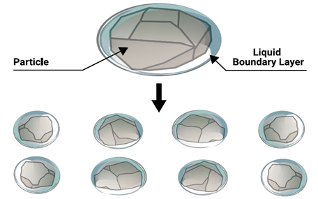
Regarding solids control efficiency, it is most beneficial to remove excavated materials in their largest state and on the very first pass through the surface equipment. Generally, operational problems associated with viscosity and drilling fluid rheology are attributed to smaller particles. Total surface area of cuttings is inversely related to cuttings size per unit volume. Imagine a cutting roughly the size of a 1-inch ball bearing. This cutting will undoubtedly absorb some of the slurry fluid due to its inherent thirst for water.
Additionally, the outer surface of the cutting has electrical charges that can attract the electrical charges on water molecules (intermolecular forces). The outcome is a cutting that is fully coated with an adsorbed boundary layer of fluid. Now imagine this cutting being broken into pieces and buried in the viscous fluid. The total surface area of all these small cuttings is greater than that of the original, larger cutting. Therefore, more mud has adsorbed to them than the original cutting.
A solids problem can also occur without an increase in solids content. The surface of the solids in any water-based slurry system is water-wet and ties up some of the available free liquid. As the solids adsorb more and more free water, viscosity increases dramatically. A simple example of this would be a cup of whole-kernel corn placed in a quart of water. When stirred, the fluid would move almost the same as before the large kernels of corn were added, and the viscosity would be nearly unchanged. If the same amount of corn were ground to corn meal and then added to the water, the resulting dough would be many times thicker than the whole-kernel corn and water.
The total amount of materials added in each case is the same, but the effect on viscosity is tremendously different. For this reason, the size of the solids in a slurry (as well as the quantity of solids) must be carefully evaluated. A general rule is to maintain a 4-6% by volume of low gravity solids in the system.
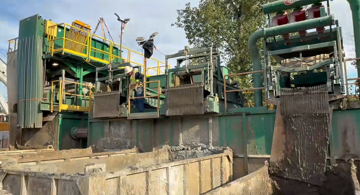
Function of the Slurry Separation System
LGS should be processed sequentially in magnitude of size (larger to smaller) along with established solids control practices. Similar to how the kidneys of the human body filter toxins out of the blood, the surface separation plant is a filtration system designed to condition the slurry to be circulated throughout the entire fluid circuit. Since all tunnel boring applications are different, some conditions require more rigid slurry specifications than others. The slurry system is usually the key to drilling the least expensive tunnel. If the slurry system is improperly treated, costs associated with non-productive time, treatment, and disposal can skyrocket.
Contamination of LGS can lead to a major increase in viscosity and density, increased slurry treatment costs, reduced Rates of Penetration (ROP), inadvertent returns, poor performance of solids removal equipment, excessive wear to pumps and parts, increased vacuum truck usage, and many more job-related issues. Any of these issues can contribute to:
- Operational and financial costs
- Project delays and downtime
- Regulatory risk
Equipment Recommendations for Removal of Low Gravity Solids
Primer
In some areas, gumbo forms and needs to be removed before the shale shakers. Gumbo is usually a form of clay (LGS) that has been hydrated and sticks together in large chunks that do not typically convey well on vibrating screens. Primers convey the sticky clay and discharge them from the system early in the solids removal section. While they are not always needed, there may be times when the TBM encounters gumbo. When this happens, they will help the separation plant efficiently process the returns from the TBM with minimal operator involvement and set up downstream separation equipment for success.
Shakers (Vibrating Screens)
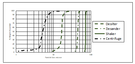
It is recommended that slurry changes be planned ahead of time due to site-specific conditions. Shakers handle 100% of the flow rate and are the first line of defense against solids contamination. However, when the slurry becomes too viscous, it causes a domino effect of problems such as reduced shaker G-Force, reduced conveyance, reduced open screen area, and wetter cuttings discharge. These are side effects of poor planning and a lack of technical evaluation of solids volume %. To determine the appropriate number of shakers and screen panel sizes for a given project, it is important to know the maximum TBM circulating rate and maximum expected ROP, along with the fluid program and anticipated ground conditions. Shaker and screen technology should allow you to separate down to the 100-75 micron range.
Hydrocyclones
Next in line are hydrocyclones, or desanders and desilters, cone-shaped devices that use centripetal force to separate larger and finer solids from the fluid, respectively. Desander/Desilters only make a D50 (50%) cut point, so optimization depends on proper equalization, piping, and flow distribution. Additionally, the pumps feeding any cone package should be sized to allow the cones to process 125-150% of the maximum TBM circulation rate. Hydrocyclones should provide for separation down to the 30 micron range.
Centrifuge
A centrifuge will be the last removal device to combat LGS. Based on mass separation, G-force, and conveyor differential speeds, the centrifuge should allow for separation down to 10 microns depending on the viscosity of the fluid, chemical treatment, retention time, and imparted Gs on the fluid. Centrifuges are typically paired with polymer mixing and dosing systems to introduce chemicals to the feed of the centrifuge to sharpen the cut point down to less than 1 microns.
What It All Means for Your Slurry System
In summary, the size range and quantity of the LGS generated in the excavation process depends on many factors and can have a significant impact on the overall function of the slurry during tunneling operations. Understanding low gravity solids and how their size and quantity will affect a slurry system, and how a sequential order of solids control equipment can reduce those effects for better overall performance is key to a lower cost, higher performing, and more successful tunneling project.
Matt Wiggins is Technical Service Rep. & Solids Control Instructor for Derrick Corporation.
Comments are closed here.